
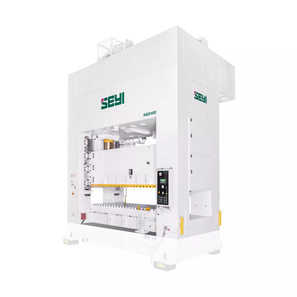
Needing a workhorse? The SAG series is the workaholic that is always taking shifts at the factory.
Its long history of power, precision, and reliability gives manufacturers the peace of mind knowing their plant can handle the toughest, grittiest jobs. Manufacturers looking to complete medium to large operations should look no further. The SAG series is engineered specifically for the most common, yet challenging operations today.
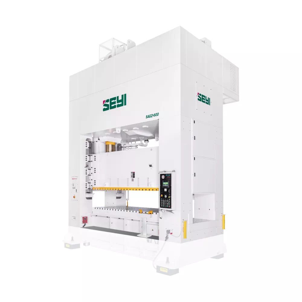
Model | SAG2-330 | SAG2-440 | SAG2-550 | ||||||
Type | S | H | S | H | S | H | |||
Capacity | U.S. Ton | 330 | 440 | 550 | |||||
Stroke Length | in | 11.81 | 7.87 | 15.75 | 9.84 | 17.72 | 9.84 | ||
Strokes per Minute | SPM | 15~30 | 25~50 | 15~26 | 25~50 | 12~22 | 25~50 | ||
Tonnage Rating Point | in | 0.51 | 0.26 | 0.51 | 0.26 | 0.51 | 0.26 | ||
Die Height | in | 23.62 | 27.56 | 27.56 | |||||
Slide Adjustment | in | 7.87 | 9.84 | 9.84 | |||||
Slide Area(LR×FB) | 1 | in | 86.61×47.24 | 98.42×55.11 | 98.42×57.09 | ||||
2 | 98.42×47.24 | 110.23×55.11 | 110.23×57.09 | ||||||
3 | 110.23×47.24 | 122.04×55.11 | 122.04×57.09 | ||||||
4 | 122.04×47.24 | 133.85×55.11 | 133.85×57.09 | ||||||
5 | 133.85×47.24 | 145.67×55.11 | 145.67×57.09 | ||||||
Bolster Area(LR×FB) | 1 | in | 86.61×53.93 | 98.42×55.11 | 98.42×57.09 | ||||
2 | 98.42×53.93 | 110.23×55.11 | 110.23×57.09 | ||||||
3 | 110.23×53.93 | 122.04×55.11 | 122.04×57.09 | ||||||
4 | 122.04×53.93 | 133.85×55.11 | 133.85×57.09 | ||||||
5 | 133.85×53.93 | 145.67×55.11 | 145.67×57.09 | ||||||
Bolster Thickness | in | 7.09 | 7.09 | 7.09 | |||||
Window Opening | Bolster Only | FB × UD | in | 39.37×19.68 | 43.31×23.62 | 47.24×23.62 | |||
Front to Back Rolling Bolster | 39.37×19.68 | 43.31×23.62 | 47.24×23.62 | ||||||
Left to Right Rolling Bolster | 65.74×27.56 | 66.93×31.5 | 68.9×31.5 | ||||||
Max. Upper Die Weight* | LBS | 6600 | 8800 | 9900 | |||||
Required Air Pressure | PSI | 85.34 | 85.34 | 85.34 | |||||
Bolster Height | Fixed Bolster | in | 33.46 | 33.46 | 33.46 | ||||
Rolling Bolster | 25.98 | 25.98 | 25.98 | ||||||
Main Motor | w/o Die Cushion | HP×P | 50×4 | 60×4 | 75×4 | ||||
w/ Die Cushion | |||||||||
Die Cushion | Type** | bellows | cylinder | cylinder | |||||
Capacity | U.S. Ton | 60.5 | 66 | 88 | |||||
Stroke Length | in | 5.91 | 7.87 | 8.66 | |||||
Adjustment | in | — | 7.87 | 8.66 | |||||
Cushion Pad Area(LR×FB) | 1 | in | 66.92×35.43 | — | 78.74×35.43 | — | 78.74×37.4 | — | |
2 | 78.74×35.43 | — | 90.55×35.43 | — | 90.55×37.4 | — | |||
3 | 90.55×35.43 | — | 102.36×35.43 | — | 102.36×37.4 | — | |||
4 | 102.36×35.43 | — | 114.17×35.43 | — | 114.17×37.4 | — | |||
Model | SAG2-660 | SAG2-880 | |||||
Type | S | H | S | H | |||
Capacity | U.S. Ton | 660 | 880 | ||||
Stroke Length | in | 17.72 | 9.84 | 17.72 | 11.81 | ||
Strokes per Minute | SPM | 12~22 | 25~50 | 10~20 | 20~40 | ||
Tonnage Rating Point | in | 0.51 | 0.26 | 0.51 | 0.26 | ||
Die Height | in | 27.56 | 31.50 | ||||
Slide Adjustment | in | 9.84 | 11.81 | ||||
Slide Area(LR×FB) | 1 | in | 98.42×61.02 | 110.23×61.02 | |||
2 | 110.23×61.02 | 122.04×61.02 | |||||
3 | 122.04×61.02 | 133.85×61.02 | |||||
4 | 133.85×61.02 | 145.67×61.02 | |||||
5 | 145.67×61.02 | 157.48×61.02 | |||||
Bolster Area(LR×FB) | 1 | in | 98.42×61.02 | 110.23×61.02 | |||
2 | 110.23×61.02 | 122.04×61.02 | |||||
3 | 122.04×61.02 | 133.85×61.02 | |||||
4 | 133.85×61.02 | 145.67×61.02 | |||||
5 | 145.67×61.02 | 157.48×61.02 | |||||
Bolster Thickness | in | 9.84 | 9.84 | ||||
Window Opening | Bolster Only | FB × UD | in | 51.18×23.62 | 59.06×27.56 | ||
Front to Back Rolling Bolster | 51.18×23.62 | 59.06×27.56 | |||||
Left to Right Rolling Bolster | 72.83×31.5 | 72.83×35.43 | |||||
Max. Upper Die Weight* | LBS | 11000 | 12100 | ||||
Required Air Pressure | PSI | 85.34 | 85.34 | ||||
Bolster Height | Fixed Bolster | in | 33.46 | 33.46 | |||
Rolling Bolster | 25.98 | 25.98 | |||||
Main Motor | w/o Die Cushion | HP×P | 75×4 | 100×4 | |||
w/ Die Cushion | |||||||
Die Cushion | Type** | cylinder | cylinder | ||||
Capacity | U.S. Ton | 110 | 132(**) | ||||
Stroke Length | in | 8.66 | 8.66 | ||||
Adjustment | in | 8.66 | 8.66 | ||||
Cushion Pad Area(LR×FB) | 1 | in | 78.74×37.4 | — | 90.55×51.18 | — | |
2 | 90.55×37.4 | — | 102.36×51.18 | — | |||
3 | 102.36×37.4 | — | 114.17×51.18 | — | |||
4 | 114.17×37.4 | — | 125.98×51.18 | — | |||
Model | SAG2-1100 | SAG2-1320 | |||||
Type | S | H | S | H | |||
Capacity | U.S. Ton | 1100 | 1320 | ||||
Stroke Length | in | 17.72 | 11.81 | 17.72 | 11.81 | ||
Strokes per Minute | SPM | 10~20 | 20~40 | 10~20 | 20~40 | ||
Tonnage Rating Point | in | 0.51 | 0.26 | 0.51 | 0.26 | ||
Die Height | in | 31.50 | 31.50 | ||||
Slide Adjustment | in | 11.81 | 11.81 | ||||
Slide Area(LR×FB) | 1 | in | 122.04×61.02 | 133.85×61.02 | |||
2 | 133.85×61.02 | 145.67×61.02 | |||||
3 | 145.67×61.02 | 157.48×61.02 | |||||
4 | 157.48×61.02 | 169.29×61.02 | |||||
5 | 169.29×61.02 | 181.1×61.02 | |||||
Bolster Area(LR×FB) | 1 | in | 122.04×61.02 | 133.85×61.02 | |||
2 | 133.85×61.02 | 145.67×61.02 | |||||
3 | 145.67×61.02 | 157.48×61.02 | |||||
4 | 157.48×61.02 | 169.29×61.02 | |||||
5 | 169.29×61.02 | 181.1×61.02 | |||||
Bolster Thickness | in | 9.84 | 11.81 | ||||
Window Opening | Bolster Only | FB × UD | in | 59.06×27.56 | 59.06×27.56 | ||
Front to Back Rolling Bolster | 59.06×27.56 | 59.06×27.56 | |||||
Left to Right Rolling Bolster | 72.83×35.43 | 72.83×35.43 | |||||
Max. Upper Die Weight* | LBS | 13200 | 15400 | ||||
Required Air Pressure | PSI | 85.34 | 85.34 | ||||
Bolster Height | Fixed Bolster | in | 33.46 | 33.46 | |||
Rolling Bolster | 29.13 | 29.13 | |||||
Main Motor | w/o Die Cushion | HP×P | 125×4 | 125×4 | |||
w/ Die Cushion | 150×4 | ||||||
Die Cushion | Type** | cylinder | cylinder | ||||
Capacity | U.S. Ton | 165 | 220 | ||||
Stroke Length | in | 8.66 | 8.66 | ||||
Adjustment | in | 8.66 | 8.66 | ||||
Cushion Pad Area(LR×FB) | 1 | in | 102.36×51.18 | — | 114.17×51.18 | — | |
2 | 114.17×51.18 | — | 125.98×51.18 | — | |||
3 | 125.98×51.18 | — | 137.8×51.18 | — | |||
4 | 137.8×51.18 | — | 149.61×51.18 | — | |||
Model | SAG4-550 | SAG4-660 | SAG4-880 | ||||||
Type | S | H | S | H | S | H | |||
Capacity | U.S. Ton | 550 | 660 | 880 | |||||
Stroke Length | in | 17.72 | 9.84 | 17.72 | 9.84 | 17.72 | 11.81 | ||
Strokes per Minute | SPM | 12~22 | 25~50 | 12~22 | 25~50 | 10~20 | 20~40 | ||
Tonnage Rating Point | in | 0.51 | 0.26 | 0.51 | 0.26 | 0.51 | 0.26 | ||
Die Height | in | 27.56 | 27.56 | 31.50 | |||||
Slide Adjustment | in | 9.84 | 9.84 | 11.81 | |||||
Slide Area(LR×FB) | 1 | in | 98.43×78.74 | 98.43×78.74 | 110.24×86.61 | ||||
2 | 110.24×78.74 | 110.24×78.74 | 122.05×86.61 | ||||||
3 | 122.05×78.74 | 122.05×78.74 | 133.86×86.61 | ||||||
4 | 133.86×78.74 | 133.86×78.74 | 145.67×86.61 | ||||||
5 | 145.67×78.74 | 145.67×78.74 | 157.48×86.61 | ||||||
Bolster Area(LR×FB) | 1 | in | 98.43×78.74 | 98.43×78.74 | 110.24×86.61 | ||||
2 | 110.24×78.74 | 110.24×78.74 | 122.05×86.61 | ||||||
3 | 122.05×78.74 | 122.05×78.74 | 133.86×86.61 | ||||||
4 | 133.86×78.74 | 133.86×78.74 | 145.67×86.61 | ||||||
5 | 145.67×78.74 | 145.67×78.74 | 157.48×86.61 | ||||||
Bolster Thickness | in | 7.09 | 9.84 | 9.84 | |||||
Window Opening | Bolster Only | FB × UD | in | 70.87×23.62 | 70.87×23.62 | 78.74×27.55 | |||
Front to Back Rolling Bolster | 70.87×23.62 | 70.87×23.62 | 78.74×27.55 | ||||||
Left to Right Rolling Bolster | 90.55×31.50 | 90.55×31.50 | 98.43×35.43 | ||||||
Max. Upper Die Weight* | LBS | 15400 | 17600 | 19800 | |||||
Required Air Pressure | PSI | 85.34 | 85.34 | 85.34 | |||||
Bolster Height | Fixed Bolster | in | 25.98 | 25.98 | 25.98 | ||||
Rolling Bolster | 25.98 | 25.98 | 25.98 | ||||||
Main Motor | w/o Die Cushion | HP×P | 75×4 | 75×4 | 100×4 | ||||
w/ Die Cushion | |||||||||
Die Cushion | Type** | cylinder | cylinder | cylinder | |||||
Capacity | U.S. Ton | 88 | 110 | – | 132(*) | — | |||
Stroke Length | in | 8.66 | 8.66 | — | 8.66 | — | |||
Adjustment | in | 8.66 | 8.66 | — | 8.66 | — | |||
Cushion Pad Area(LR×FB) | 1 | in | 78.74×51.18 | 78.74×51.18 | — | 90.55×59.06 | — | ||
2 | 90.55×51.18 | 90.55×51.18 | — | 102.36×59.06 | — | ||||
3 | 102.36×51.18 | 102.36×51.18 | — | 114.17×59.06 | — | ||||
4 | 114.17×51.18 | 114.17×51.18 | — | 125.98×59.06 | — | ||||
Model | SAG4-1100 | SAG4-1320 | |||||
Type | S | H | S | H | |||
Capacity | U.S. Ton | 1100 | 1320 | ||||
Stroke Length | in | 17.72 | 11.81 | 17.72 | 11.81 | ||
Strokes per Minute | SPM | 10~20 | 20~40 | 10~20 | 20~40 | ||
Tonnage Rating Point | in | 0.51 | 0.26 | 0.51 | 0.26 | ||
Die Height | in | 31.50 | 31.50 | ||||
Slide Adjustment | in | 11.81 | 11.81 | ||||
Slide Area(LR×FB) | 1 | in | 122.05×86.61 | 133.86×86.61 | |||
2 | 133.86×86.61 | 145.67×86.61 | |||||
3 | 145.67×86.61 | 157.48×86.61 | |||||
4 | 157.48×86.61 | 169.29×86.61 | |||||
5 | 169.29×86.61 | 181.1×86.61 | |||||
Bolster Area(LR×FB) | 1 | in | 122.05×86.61 | 133.86×86.61 | |||
2 | 133.86×86.61 | 145.67×86.61 | |||||
3 | 145.67×86.61 | 157.48×86.61 | |||||
4 | 157.48×86.61 | 169.29×86.61 | |||||
5 | 169.29×86.61 | 181.1×86.61 | |||||
Bolster Thickness | in | 9.84 | 11.81 | ||||
Window Opening | Bolster Only | FB × UD | in | 78.74×27.55 | 78.74×27.55 | ||
Front to Back Rolling Bolster | 78.74×27.55 | 78.74×27.55 | |||||
Left to Right Rolling Bolster | 98.43×35.43 | 98.43×35.43 | |||||
Max. Upper Die Weight* | LBS | 19800 | 22000 | ||||
Required Air Pressure | PSI | 85.34 | 85.34 | ||||
Bolster Height | Fixed Bolster | in | 29.13 | 29.13 | |||
Rolling Bolster | 29.13 | 29.13 | |||||
Main Motor | w/o Die Cushion | HP×P | 125×4 | 125×4 | |||
w/ Die Cushion | 150×4 | ||||||
Die Cushion | Type** | cylinder | cylinder | ||||
Capacity | U.S. Ton | 165 | — | 220 | — | ||
Stroke Length | in | 8.66 | — | 8.66 | — | ||
Adjustment | in | 8.66 | — | 8.66 | — | ||
Cushion Pad Area(LR×FB) | 1 | in | 223.62×59.06 | — | 114.17×59.06 | — | |
2 | 114.17×59.06 | — | 125.98×59.06 | — | |||
3 | 125.98×59.06 | — | 137.8×59.06 | — | |||
4 | 137.8×59.06 | — | 149.61×59.06 | — | |||
* Upper die weight may vary in table size. Please contact your sales representative for more information.
** For selecting 132T, 165T and 220T air cylinder die cushions, bolster area in FB should be at least 66.93in.
*** For selecting 264T, 330T air cylinder die cushions, bolster area in FB should be at least 74.80in.
**** For SAG2-880-1, only 110T die cushion is available.
* For SAG4-880-1, only 110T die cushion is available
※ Slide and bolster area up to 216.53×61.02in by request.
※ This specification is subject to change without notice.
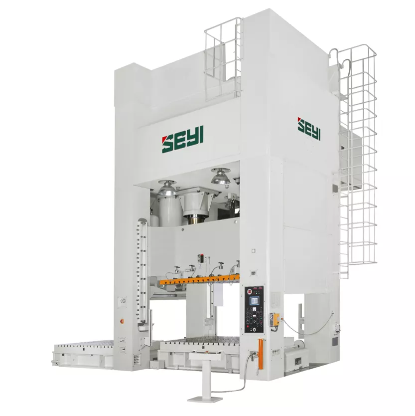
As an excellent equipment for processing high-tensile steel panels, the SE series with tough rigidity is mainly applied with large dies in automotive industry. The model adopts design of eccentric gear drive component and 8-point guided slide for high precision. The design of energy and electricity conservation allows saving more than 20% of energy and the large overload capacity extends the lifetime of use.
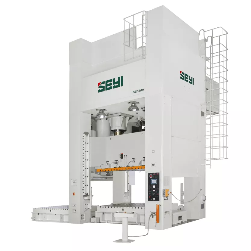
Model | SE2-440 | SE2-550 | SE2-660 | ||||||
Type | S | H | S | H | S | H | |||
Capacity | U.S. Ton | 440 | 550 | 660 | |||||
Stroke Length | in | 19.69 | 19.69 | 19.69 | |||||
Strokes per Minute | SPM | 15~26 | 12~24 | 12~22 | |||||
Tonnage Rating Point | in | 0.51 | 0.26 | 0.51 | 0.26 | 0.51 | 0.26 | ||
Die Height | in | 27.56 | 31.50 | 31.50 | |||||
Slide Adjustment | in | 11.81 | 15.75 | 15.75 | |||||
Slide Area(LR×FB) | 1 | in | 98.43×55.12 | 98.43×57.09 | 98.43×61.02 | ||||
2 | 110.24×55.12 | 110.24×57.09 | 110.24×61.02 | ||||||
3 | 122.05×55.12 | 122.05×57.09 | 122.05×61.02 | ||||||
4 | 133.86×55.12 | 133.86×57.09 | 133.86×61.02 | ||||||
5 | 145.67×55.12 | 145.67×57.09 | 145.67×61.02 | ||||||
Bolster Area(LR×FB) | 1 | in | 98.43×55.12 | 98.43×57.09 | 98.43×61.02 | ||||
2 | 110.24×55.12 | 110.24×57.09 | 110.24×61.02 | ||||||
3 | 122.05×55.12 | 122.05×57.09 | 122.05×61.02 | ||||||
4 | 133.86×55.12 | 133.86×57.09 | 133.86×61.02 | ||||||
5 | 145.67×55.12 | 145.67×57.09 | 145.67×61.02 | ||||||
Bolster Thickness | in | 7.09 | 7.09 | 9.84 | |||||
Window Opening | Bolster Only | FB × UD | in | 47.24×23.62 | 47.24×27.56 | 53.15×27.56 | |||
Front to Back Rolling Bolster | 47.24×23.62 | 47.24×27.56 | 53.15×27.56 | ||||||
Left to Right Rolling Bolster | 66.93×31.5 | 68.90×35.43 | 72.83×35.43 | ||||||
Max. Upper Die Weight* | LBS | 11000 | 13200 | 13200 | |||||
Required Air Pressure | PSI | 85.34 | 85.34 | 85.34 | |||||
Bolster Height | Fixed Bolster | in | 33.46 | 33.46 | 33.46 | ||||
Rolling Bolster | 25.98 | 25.98 | 25.98 | ||||||
Main Motor | w/o Die Cushion | HP×P | 60×4 | 75×4 | 75×4 | ||||
w/ Die Cushion | |||||||||
Die Cushion | Type | cylinder | cylinder | cylinder | |||||
Capacity | U.S. Ton | 66 | 88 | 110 | |||||
Stroke Length | in | 7.87 | 8.66 | 8.66 | |||||
Adjustment | in | 7.87 | 8.66 | 8.66 | |||||
Cushion Pad Area(LR×FB) | 1 | in | 78.74×35.43 | – | 78.74×37.4 | – | 78.74×37.4 | – | |
2 | 90.55×35.43 | – | 90.55×37.4 | – | 90.55×37.4 | – | |||
3 | 102.36×35.43 | – | 102.36×37.4 | – | 102.36×37.4 | – | |||
4 | 114.17×35.43 | – | 114.17×37.4 | – | 114.17×37.4 | – | |||
Model | SE2-880 | SE2-1100 | SE2-1320 | |||
Type | S | S | S | |||
Capacity | U.S. Ton | 880 | 1100 | 1320 | ||
Stroke Length | in | 23.62 | 23.62 | 31.50 | ||
Strokes per Minute | SPM | 10~18 | 10~18 | 10~18 | ||
Tonnage Rating Point | in | 0.51 | 0.51 | 0.51 | ||
Die Height | in | 39.37 | 39.37 | 43.31 | ||
Slide Adjustment | in | 15.75 | 15.75 | 19.69 | ||
Slide Area(LR×FB) | 1 | in | 110.24×66.93 | 122.05×66.93 | 133.86×66.93 | |
2 | 122.05×66.93 | 133.86×66.93 | 145.67×66.93 | |||
3 | 133.86×66.93 | 145.67×66.93 | 157.48×66.93 | |||
4 | 145.67×66.93 | 157.48×66.93 | 169.29×66.93 | |||
5 | 157.48×66.93 | 169.29×66.93 | 181.1×66.93 | |||
Bolster Area(LR×FB) | 1 | in | 110.24×66.93 | 122.05×66.93 | 133.86×66.93 | |
2 | 122.05×66.93 | 133.86×66.93 | 145.67×66.93 | |||
3 | 133.86×66.93 | 145.67×66.93 | 157.48×66.93 | |||
4 | 145.67×66.93 | 157.48×66.93 | 169.29×66.93 | |||
5 | 157.48×66.93 | 169.29×66.93 | 181.1×66.93 | |||
Bolster Thickness | in | 9.84 | 9.84 | 11.81 | ||
Window Opening | Bolster Only | FB × UD | in | 59.06×35.43 | 59.06×35.43 | 59.06×39.37 |
Front to Back Rolling Bolster | 59.06×35.43 | 59.06×35.43 | 59.06×39.37 | |||
Left to Right Rolling Bolster | 78.74×43.31 | 78.74×43.31 | 78.74×47.24 | |||
Max. Upper Die Weight* | LBS | 15400 | 15400 | 17600 | ||
Required Air Pressure | PSI | 85.34 | 85.34 | 85.34 | ||
Bolster Height | Fixed Bolster | in | 33.46 | 33.46 | 33.46 | |
Rolling Bolster | 25.98 | 29.13 | 29.13 | |||
Main Motor | w/o Die Cushion | HP×P | 100×4 | 125×4 | 125×4 | |
w/ Die Cushion | 150×4 | |||||
Die Cushion | Type | cylinder | cylinder | cylinder | ||
Capacity | U.S. Ton | 132** | 165 | 220 | ||
Stroke Length | in | 8.66 | 8.66 | 8.66 | ||
Adjustment | in | 8.66 | 8.66 | 8.66 | ||
Cushion Pad Area(LR×FB) | 1 | in | 90.55×51.18 | 102.36×51.18 | 114.17×51.18 | |
2 | 102.36×51.18 | 114.17×51.18 | 125.98×51.18 | |||
3 | 114.17×51.18 | 125.98×51.18 | 137.8×51.18 | |||
4 | 125.98×51.18 | 137.8×51.18 | 149.61×51.18 | |||
Model | SE4-550 | SE4-660 | SE4-880 | |||
Type | S | S | S | |||
Capacity | U.S. Ton | 550 | 660 | 880 | ||
Stroke Length | in | 19.69 | 19.69 | 23.62 | ||
Strokes per Minute | SPM | 12~24 | 12~22 | 10~20 | ||
Tonnage Rating Point | in | 0.51 | 0.51 | 0.51 | ||
Die Height | in | 31.50 | 31.50 | 39.37 | ||
Slide Adjustment | in | 15.75 | 15.75 | 15.75 | ||
Slide Area(LR×FB) | 1 | in | 98.43×78.74 | 98.43×78.74 | 110.24×86.61 | |
2 | 110.24×78.74 | 110.24×78.74 | 122.05×86.61 | |||
3 | 122.05×78.74 | 122.05×78.74 | 133.86×86.61 | |||
4 | 133.86×78.74 | 133.86×78.74 | 145.67×86.61 | |||
5 | 145.67×78.74 | 145.67×78.74 | 157.48×86.61 | |||
Bolster Area(LR×FB) | 1 | in | 98.43×78.74 | 98.43×78.74 | 110.24×86.61 | |
2 | 110.24×78.74 | 110.24×78.74 | 122.05×86.61 | |||
3 | 122.05×78.74 | 122.05×78.74 | 133.86×86.61 | |||
4 | 133.86×78.74 | 133.86×78.74 | 145.67×86.61 | |||
5 | 145.67×78.74 | 145.67×78.74 | 157.48×86.61 | |||
Bolster Thickness | in | 7.09 | 9.84 | 9.84 | ||
Window Opening | Bolster Only | FB × UD | in | 70.87×27.56 | 70.87×27.56 | 78.74×35.43 |
Front to Back Rolling Bolster | 70.87×27.56 | 70.87×27.56 | 78.74×35.43 | |||
Left to Right Rolling Bolster | 90.55×35.43 | 90.55×35.43 | 98.43×43.31 | |||
Max. Upper Die Weight* | LBS | 17600 | 19800 | 22000 | ||
Required Air Pressure | PSI | 85.34 | 85.34 | 85.34 | ||
Bolster Height | Fixed Bolster | in | 25.98 | 25.98 | 25.98 | |
Rolling Bolster | 25.98 | 25.98 | 25.98 | |||
Main Motor | w/o Die Cushion | HP×P | 75×4 | 75×4 | 100×4 | |
w/ Die Cushion | ||||||
Die Cushion | Type | cylinder | cylinder | cylinder | ||
Capacity | U.S. Ton | 88 | 110 | 132(*) | ||
Stroke Length | in | 8.66 | 8.66 | 9.84 | ||
Adjustment | in | 8.66 | 8.66 | 9.84 | ||
Cushion Pad Area(LR×FB) | 1 | in | 78.74×51.18 | 78.74×51.18 | 90.55×59.06 | |
2 | 90.55×51.18 | 90.55×51.18 | 102.36×59.06 | |||
3 | 102.36×51.18 | 102.36×51.18 | 114.17×59.06 | |||
4 | 114.17×51.18 | 114.17×51.18 | 125.98×59.06 | |||
Model | SE4-1100 | SE4-1320 | SE4-1760 | |||
Type | S | S | S | |||
Capacity | U.S. Ton | 1100 | 1320 | 1760 | ||
Stroke Length | in | 23.62 | 31.50 | 31.50 | ||
Strokes per Minute | SPM | 10~20 | 10~20 | 10~20 | ||
Tonnage Rating Point | in | 0.51 | 0.51 | 0.51 | ||
Die Height | in | 39.37 | 43.31 | 47.24 | ||
Slide Adjustment | in | 15.75 | 19.69 | 19.69 | ||
Slide Area(LR×FB) | 1 | in | 122.05×86.61 | 133.86×86.61 | 133.86×86.61 | |
2 | 133.86×86.61 | 145.67×86.61 | 145.67×86.61 | |||
3 | 145.67×86.61 | 157.48×86.61 | 157.48×86.61 | |||
4 | 157.48×86.61 | 169.29×86.61 | 169.29×86.61 | |||
5 | 169.29×86.61 | 181.1×86.61 | 181.1×86.61 | |||
Bolster Area(LR×FB) | 1 | in | 122.05×86.61 | 133.86×86.61 | 133.86×86.61 | |
2 | 133.86×86.61 | 145.67×86.61 | 145.67×86.61 | |||
3 | 145.67×86.61 | 157.48×86.61 | 157.48×86.61 | |||
4 | 157.48×86.61 | 169.29×86.61 | 169.29×86.61 | |||
5 | 169.29×86.61 | 181.1×86.61 | 181.1×86.61 | |||
Bolster Thickness | in | 9.84 | 11.81 | 11.81 | ||
Window Opening | Bolster Only | FB × UD | in | 78.74×35.43 | 78.74×39.37 | 78.74×43.31 |
Front to Back Rolling Bolster | 78.74×35.43 | 78.74×39.37 | 78.74×43.31 | |||
Left to Right Rolling Bolster | 98.43×43.31 | 98.43×47.24 | 98.43×51.18 | |||
Max. Upper Die Weight* | LBS | 22000 | 24200 | 28600 | ||
Required Air Pressure | PSI | 85.34 | 85.34 | 85.34 | ||
Bolster Height | Fixed Bolster | in | 29.13 | 29.13 | 29.13 | |
Rolling Bolster | 29.13 | 29.13 | 29.13 | |||
Main Motor | w/o Die Cushion | HP×P | 125×4 | 125×4 | 175×4 | |
w/ Die Cushion | 150×4 | 200×4 | ||||
Die Cushion | Type | cylinder | cylinder | cylinder | ||
Capacity | U.S. Ton | 165 | 220 | 264 | ||
Stroke Length | in | 9.84 | 9.84 | 9.84 | ||
Adjustment | in | 9.84 | 9.84 | 9.84 | ||
Cushion Pad Area(LR×FB) | 1 | in | 102.36×59.06 | 114.17×59.06 | 114.17×59.06 | |
2 | 114.17×59.06 | 125.98×59.06 | 125.98×59.06 | |||
3 | 125.98×59.06 | 137.8×59.06 | 137.8×59.06 | |||
4 | 137.8×59.06 | 149.61×59.06 | 149.61×59.06 | |||
Model | SE4-2200 | SE4-2640 | |||
Type | S | S | |||
Capacity | U.S. Ton | 2200 | 2640 | ||
Stroke Length | in | 35.43 | 39.37 | ||
Strokes per Minute | SPM | 10~20 | 10~20 | ||
Tonnage Rating Point | in | 0.51 | 0.51 | ||
Die Height | in | 51.18 | 55.12 | ||
Slide Adjustment | in | 23.62 | 23.62 | ||
Slide Area(LR×FB) | 1 | in | 157.48×86.61 | 157.48×86.61 | |
2 | 169.29×86.61 | 169.29×86.61 | |||
3 | 181.1×86.61 | 181.1×86.61 | |||
4 | 192.91×86.61 | 192.91×86.61 | |||
5 | 204.72×86.61 | 204.72×86.61 | |||
Bolster Area(LR×FB) | 1 | in | 157.48×86.61 | 157.48×86.61 | |
2 | 169.29×86.61 | 169.29×86.61 | |||
3 | 181.1×86.61 | 181.1×86.61 | |||
4 | 192.91×86.61 | 192.91×86.61 | |||
5 | 204.72×86.61 | 204.72×86.61 | |||
Bolster Thickness | in | 11.81 | 11.81 | ||
Window Opening | Bolster Only | FB × UD | in | 78.74×47.24 | 78.74×51.18 |
Front to Back Rolling Bolster | 78.74×47.24 | 78.74×51.18 | |||
Left to Right Rolling Bolster | 98.43×55.12 | 98.43×59.06 | |||
Max. Upper Die Weight* | LBS | 33000 | 44000 | ||
Required Air Pressure | PSI | 85.34 | 85.34 | ||
Bolster Height | Fixed Bolster | in | 29.13 | 29.13 | |
Rolling Bolster | 29.13 | 29.13 | |||
Main Motor | w/o Die Cushion | HP×P | 200 ×4 | 250 ×4 | |
w/ Die Cushion | 200 ×4 | 300 ×4 | |||
Die Cushion | Type** | cylinder | cylinder | ||
Capacity | U.S. Ton | 330 | 330 | ||
Stroke Length | in | 11.81 | 11.81 | ||
Adjustment | in | 11.81 | 11.81 | ||
Cushion Pad Area(LR×FB) | 1 | in | 137.8×59.06 | 137.8×59.06 | |
2 | 149.61×59.06 | 149.61×59.06 | |||
3 | 161.42×59.06 | 161.42×59.06 | |||
4 | 173.23×59.06 | 173.23×59.06 | |||
* Upper die weight may vary in table size. Please contact your sales representative for more information.
** For selecting 132T, 165T and 220T air cylinder die cushions, bolster area in FB should be at least 66.93in.
*** For SE2-880-1, only 110T die cushion is available.
* For SE4-880-1, only 110T die cushion is available
※ Slide and bolster area up to 216.53×61.02in by request.
※ This specification is subject to change without notice.
This series is the prime choice for large parts forming, which makes it applicable for automotive parts forming. The crank shaft and connecting rods are adopted to drive the gear component. The soft contact during forming extensively reduces vibration, noise and heat, as well as extending die lifetime. The design of low energy consumption can effectively save more than 20% of energy.
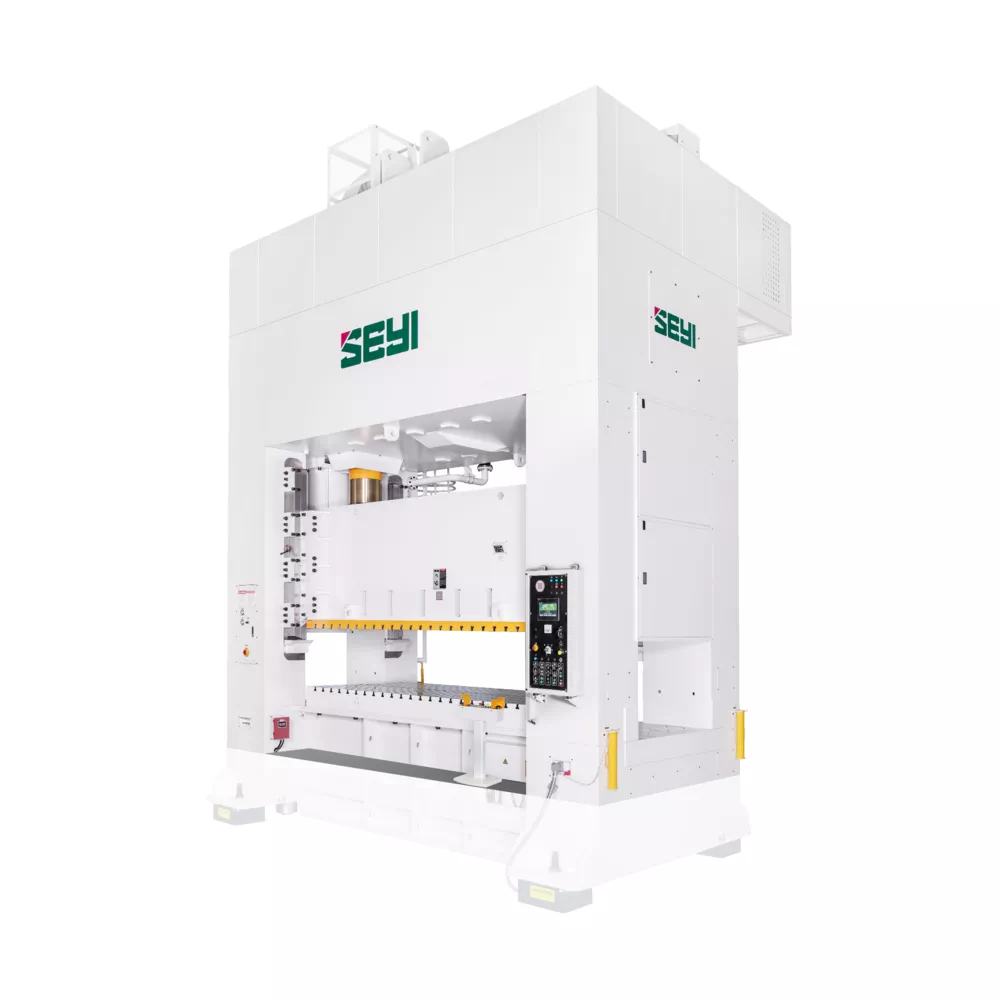
Model | SLG2-330 | SLG2-440 | SLG2-550 | ||||||
Type | S | H | S | H | S | H | |||
Capacity | U.S. Ton | 330 | 440 | 550 | |||||
Stroke Length | in | 11.81 | 7.87 | 15.75 | 9.84 | 17.72 | 9.84 | ||
Strokes per Minute | SPM | 15~30 | 25~50 | 15~26 | 25~50 | 12~22 | 25~50 | ||
Tonnage Rating Point | in | 0.51 | 0.26 | 0.51 | 0.26 | 0.51 | 0.26 | ||
Die Height | in | 23.62 | 27.56 | 27.56 | |||||
Slide Adjustment | in | 7.87 | 9.84 | 9.84 | |||||
Slide Area(LR×FB) | 1 | in | 86.61×47.24 | 98.43×55.12 | 98.43×57.09 | ||||
2 | 98.43×47.24 | 110.24×55.12 | 110.24×57.09 | ||||||
3 | 110.24×47.24 | 122.05×55.12 | 122.05×57.09 | ||||||
4 | 122.05×47.24 | 133.86×55.12 | 133.86×57.09 | ||||||
5 | 133.86×47.24 | 145.67×55.12 | 145.67×57.09 | ||||||
Bolster Area(LR×FB) | 1 | in | 86.61×53.94 | 98.43×55.12 | 98.43×57.09 | ||||
2 | 98.43×53.94 | 110.24×55.12 | 110.24×57.09 | ||||||
3 | 110.24×53.94 | 122.05×55.12 | 122.05×57.09 | ||||||
4 | 122.05×53.94 | 133.86×55.12 | 133.86×57.09 | ||||||
5 | 133.86×53.94 | 145.67×55.12 | 145.67×57.09 | ||||||
Bolster Thickness | in | 7.09 | 7.09 | 7.09 | |||||
Window Opening | Bolster Only | FB × UD | in | 39.37×19.69 | 43.31×23.62 | 47.24×23.62 | |||
Front to Back Rolling Bolster | 39.37×19.69 | 43.31×23.62 | 47.24×23.62 | ||||||
Left to Right Rolling Bolster | 65.74×27.56 | 66.93×31.5 | 68.90×31.5 | ||||||
Max. Upper Die Weight* | LBS | 6600 | 8800 | 9900 | |||||
Required Air Pressure | PSI | 85.34 | 85.34 | 85.34 | |||||
Bolster Height | Fixed Bolster | in | 33.46 | 33.46 | 33.46 | ||||
Rolling Bolster | 25.98 | 25.98 | 25.98 | ||||||
Main Motor | w/o Die Cushion | HP×P | 50×4 | 60×4 | 75×4 | ||||
w/ Die Cushion | |||||||||
Die Cushion | Type** | bellows | cylinder | cylinder | |||||
Capacity | U.S. Ton | 60.5 | 66 | 88 | |||||
Stroke Length | in | 5.91 | 7.87 | 8.66 | |||||
Adjustment | in | — | 7.87 | 8.66 | |||||
Cushion Pad Area(LR×FB) | 1 | in | 66.93×35.43 | — | 78.74×35.43 | — | 78.74×37.4 | — | |
2 | 78.74×35.43 | — | 90.55×35.43 | — | 90.55×37.4 | — | |||
3 | 90.55×35.43 | — | 102.36×35.43 | — | 102.36×37.4 | — | |||
4 | 102.36×35.43 | — | 114.17×35.43 | — | 114.17×37.4 | — | |||
Model | SLG2-660 | SLG2-880 | |||||
Type | S | H | S | H | |||
Capacity | U.S. Ton | 660 | 880 | ||||
Stroke Length | in | 17.72 | 9.84 | 17.72 | 11.81 | ||
Strokes per Minute | SPM | 12~22 | 25~50 | 10~20 | 20~40 | ||
Tonnage Rating Point | in | 0.51 | 0.26 | 0.51 | 0.26 | ||
Die Height | in | 27.56 | 31.50 | ||||
Slide Adjustment | in | 9.84 | 11.81 | ||||
Slide Area(LR×FB) | 1 | in | 98.43×61.02 | 110.24×61.02 | |||
2 | 110.24×61.02 | 122.05×61.02 | |||||
3 | 122.05×61.02 | 133.86×61.02 | |||||
4 | 133.86×61.02 | 145.67×61.02 | |||||
5 | 145.67×61.02 | 157.48×61.02 | |||||
Bolster Area(LR×FB) | 1 | in | 98.43×61.02 | 110.24×61.02 | |||
2 | 110.24×61.02 | 122.05×61.02 | |||||
3 | 122.05×61.02 | 133.86×61.02 | |||||
4 | 133.86×61.02 | 145.67×61.02 | |||||
5 | 145.67×61.02 | 157.48×61.02 | |||||
Bolster Thickness | in | 9.84 | 9.84 | ||||
Window Opening | Bolster Only | FB × UD | in | 51.18×23.62 | 59.06×27.56 | ||
Front to Back Rolling Bolster | 51.18×23.62 | 59.06×27.56 | |||||
Left to Right Rolling Bolster | 72.83×31.5 | 72.83×35.43 | |||||
Max. Upper Die Weight* | LBS | 11000 | 12100 | ||||
Required Air Pressure | PSI | 85.34 | 85.34 | ||||
Bolster Height | Fixed Bolster | in | 33.46 | 33.46 | |||
Rolling Bolster | 25.98 | 25.98 | |||||
Main Motor | w/o Die Cushion | HP×P | 75×4 | 100×4 | |||
w/ Die Cushion | |||||||
Die Cushion | Type** | cylinder | cylinder | ||||
Capacity | U.S. Ton | 110 | 132(**) | ||||
Stroke Length | in | 8.66 | 8.66 | ||||
Adjustment | in | 8.66 | 8.66 | ||||
Cushion Pad Area(LR×FB) | 1 | in | 78.74×37.4 | — | 90.55×51.18 | — | |
2 | 90.55×37.4 | — | 102.36×51.18 | — | |||
3 | 102.36×37.4 | — | 114.17×51.18 | — | |||
4 | 114.17×37.4 | — | 125.98×51.18 | — | |||
Model | SLG2-1100 | SLG2-1320 | |||||
Type | S | H | S | H | |||
Capacity | U.S. Ton | 1100 | 1320 | ||||
Stroke Length | in | 17.72 | 11.81 | 17.72 | 11.81 | ||
Strokes per Minute | SPM | 10~20 | 20~40 | 10~20 | 20~40 | ||
Tonnage Rating Point | in | 0.51 | 0.26 | 0.51 | 0.26 | ||
Die Height | in | 31.50 | 31.50 | ||||
Slide Adjustment | in | 11.81 | 11.81 | ||||
Slide Area(LR×FB) | 1 | in | 122.05×61.02 | 133.86×61.02 | |||
2 | 133.86×61.02 | 145.67×61.02 | |||||
3 | 145.67×61.02 | 157.48×61.02 | |||||
4 | 157.48×61.02 | 169.29×61.02 | |||||
5 | 169.29×61.02 | 181.1×61.02 | |||||
Bolster Area(LR×FB) | 1 | in | 122.05×61.02 | 133.86×61.02 | |||
2 | 133.86×61.02 | 145.67×61.02 | |||||
3 | 145.67×61.02 | 157.48×61.02 | |||||
4 | 157.48×61.02 | 169.29×61.02 | |||||
5 | 169.29×61.02 | 181.1×61.02 | |||||
Bolster Thickness | in | 9.84 | 11.81 | ||||
Window Opening | Bolster Only | FB × UD | in | 59.06×27.56 | 59.06×27.56 | ||
Front to Back Rolling Bolster | 59.06×27.56 | 59.06×27.56 | |||||
Left to Right Rolling Bolster | 72.83×35.43 | 72.83×35.43 | |||||
Max. Upper Die Weight* | LBS | 13200 | 15400 | ||||
Required Air Pressure | PSI | 85.34 | 85.34 | ||||
Bolster Height | Fixed Bolster | in | 33.46 | 33.46 | |||
Rolling Bolster | 29.13 | 29.13 | |||||
Main Motor | w/o Die Cushion | HP×P | 125×4 | 125×4 | |||
w/ Die Cushion | 150×4 | ||||||
Die Cushion | Type** | cylinder | cylinder | ||||
Capacity | U.S. Ton | 165 | 220 | ||||
Stroke Length | in | 8.66 | 8.66 | ||||
Adjustment | in | 8.66 | 8.66 | ||||
Cushion Pad Area(LR×FB) | 1 | in | 102.36×51.18 | — | 114.17×51.18 | — | |
2 | 114.17×51.18 | — | 125.98×51.18 | — | |||
3 | 125.98×51.18 | — | 137.8×51.18 | — | |||
4 | 137.8×51.18 | — | 149.61×51.18 | — | |||
Model | SLG4-550 | SLG4-660 | SLG4-880 | ||||||
Type | S | H | S | H | S | H | |||
Capacity | U.S. Ton | 550 | 660 | 880 | |||||
Stroke Length | in | 17.72 | 9.84 | 17.72 | 9.84 | 17.72 | 11.81 | ||
Strokes per Minute | SPM | 12~22 | 25~50 | 12~22 | 25~50 | 10~20 | 20~40 | ||
Tonnage Rating Point | in | 0.51 | 0.26 | 0.51 | 0.26 | 0.51 | 0.26 | ||
Die Height | in | 27.56 | 27.56 | 31.50 | |||||
Slide Adjustment | in | 9.84 | 9.84 | 11.81 | |||||
Slide Area(LR×FB) | 1 | in | 98.43×78.74 | 98.43×78.74 | 110.24×86.61 | ||||
2 | 110.24×78.74 | 110.24×78.74 | 122.05×86.61 | ||||||
3 | 122.05×78.74 | 122.05×78.74 | 133.86×86.61 | ||||||
4 | 133.86×78.74 | 133.86×78.74 | 145.67×86.61 | ||||||
5 | 145.67×78.74 | 145.67×78.74 | 157.48×86.61 | ||||||
Bolster Area(LR×FB) | 1 | in | 98.43×78.74 | 98.43×78.74 | 110.24×86.61 | ||||
2 | 110.24×78.74 | 110.24×78.74 | 122.05×86.61 | ||||||
3 | 122.05×78.74 | 122.05×78.74 | 133.86×86.61 | ||||||
4 | 133.86×78.74 | 133.86×78.74 | 145.67×86.61 | ||||||
5 | 145.67×78.74 | 145.67×78.74 | 157.48×86.61 | ||||||
Bolster Thickness | in | 7.09 | 9.84 | 9.84 | |||||
Window Opening | Bolster Only | FB × UD | in | 70.87×23.62 | 70.87×23.62 | 78.74×27.56 | |||
Front to Back Rolling Bolster | 70.87×23.62 | 70.87×23.62 | 78.74×27.56 | ||||||
Left to Right Rolling Bolster | 90.55×31.5 | 90.55×31.5 | 98.43×35.43 | ||||||
Max. Upper Die Weight* | LBS | 15400 | 17600 | 19800 | |||||
Required Air Pressure | PSI | 85.34 | 85.34 | 85.34 | |||||
Bolster Height | Fixed Bolster | in | 25.98 | 25.98 | 25.98 | ||||
Rolling Bolster | 25.98 | 25.98 | 25.98 | ||||||
Main Motor | w/o Die Cushion | HP×P | 75×4 | 75×4 | 100×4 | ||||
w/ Die Cushion | |||||||||
Die Cushion | Type** | cylinder | cylinder | cylinder | |||||
Capacity | U.S. Ton | 88 | 110 | — | 132(*) | — | |||
Stroke Length | in | 8.66 | 8.66 | — | 8.66 | — | |||
Adjustment | in | 8.66 | 8.66 | — | 8.66 | — | |||
Cushion Pad Area(LR×FB) | 1 | in | 78.74×51.18 | 78.74×51.18 | – | 90.55×59.06 | — | ||
2 | 90.55×51.18 | 90.55×51.18 | – | 102.36×59.06 | — | ||||
3 | 102.36×51.18 | 102.36×51.18 | – | 114.17×59.06 | — | ||||
4 | 114.17×51.18 | 114.17×51.18 | – | 125.98×59.06 | — | ||||
Model | SLG4-1100 | SLG4-1320 | |||||||
Type | S | H | S | H | |||||
Capacity | U.S. Ton | 1100 | 1320 | ||||||
Stroke Length | in | 17.72 | 11.81 | 17.72 | 11.81 | ||||
Strokes per Minute | SPM | 10~20 | 20~40 | 10~20 | 20~40 | ||||
Tonnage Rating Point | in | 0.51 | 0.26 | 0.51 | 0.26 | ||||
Die Height | in | 31.50 | 31.50 | ||||||
Slide Adjustment | in | 11.81 | 11.81 | ||||||
Slide Area(LR×FB) | 1 | in | 122.05×86.61 | 133.86×86.61 | |||||
2 | 133.86×86.61 | 145.67×86.61 | |||||||
3 | 145.67×86.61 | 157.48×86.61 | |||||||
4 | 157.48×86.61 | 169.29×86.61 | |||||||
5 | 169.29×86.61 | 181.1×86.61 | |||||||
Bolster Area(LR×FB) | 1 | in | 122.05×86.61 | 133.86×86.61 | |||||
2 | 133.86×86.61 | 145.67×86.61 | |||||||
3 | 145.67×86.61 | 157.48×86.61 | |||||||
4 | 157.48×86.61 | 169.29×86.61 | |||||||
5 | 169.29×86.61 | 181.1×86.61 | |||||||
Bolster Thickness | in | 9.84 | 11.81 | ||||||
Window Opening | Bolster Only | FB × UD | in | 78.74×27.56 | 78.74×27.56 | ||||
Front to Back Rolling Bolster | 78.74×27.56 | 78.74×27.56 | |||||||
Left to Right Rolling Bolster | 98.43×35.43 | 98.43×35.43 | |||||||
Max. Upper Die Weight* | LBS | 19800 | 22000 | ||||||
Required Air Pressure | PSI | 85.34 | 85.34 | ||||||
Bolster Height | Fixed Bolster | in | 29.13 | 29.13 | |||||
Rolling Bolster | 29.13 | 29.13 | |||||||
Main Motor | w/o Die Cushion | HP×P | 125×4 | 125×4 | 150×4 | ||||
w/ Die Cushion | |||||||||
Die Cushion | Type** | cylinder | cylinder | cylinder | |||||
Capacity | U.S. Ton | 165 | — | 220 | — | ||||
Stroke Length | in | 8.66 | — | 8.66 | — | ||||
Adjustment | in | 8.66 | — | 8.66 | — | ||||
Cushion Pad Area(LR×FB) | 1 | in | 102.36×59.06 | — | 114.17×59.06 | — | |||
2 | 114.17×59.06 | — | 125.98×59.06 | — | |||||
3 | 125.98×59.06 | — | 137.8×59.06 | — | |||||
4 | 137.8×59.06 | — | 149.61×59.06 | — | |||||
* Upper die weight may vary in table size. Please contact your sales representative for more information.
** For selecting 132T, 165T and 220T air cylinder die cushions, bolster area in FB should be at least 66.93in.
*** For selecting 264T, 330T air cylinder die cushions, bolster area in FB should be at least 74.80in.
**** For SLG2-880-1, only 110T die cushion is available.
* For SLG4-880-1, only 110T die cushion is available
※ Slide and bolster area up to 216.53×61.02in by request.
※ This specification is subject to change without notice.
The prime choice of press equipment for forming process of large pieces, which makes it applicable for forming of large automotive parts. The eccentric gear and connecting rods are adopted for the drive component. The design of low energy consumption can effectively save more than 20% of energy.
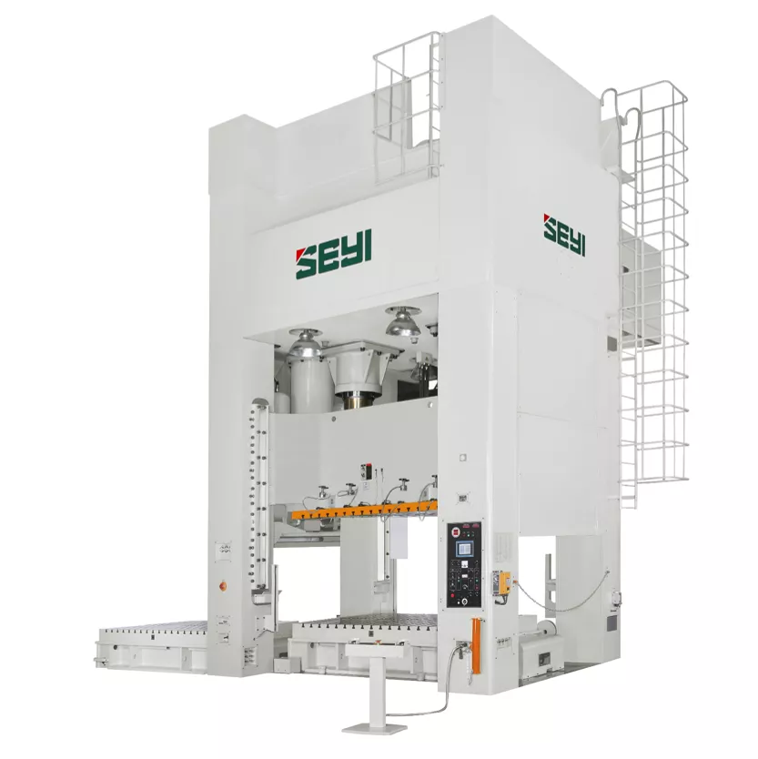
Model | SEL2-440 | SEL2-550 | SEL2-660 | ||||||
Type | S | H | S | H | S | H | |||
Capacity | U.S. Ton | 440 | 550 | 660 | |||||
Stroke Length | in | 19.69 | 19.69 | 19.69 | |||||
Strokes per Minute | SPM | 15~26 | 12~24 | 12~22 | |||||
Tonnage Rating Point | in | 0.51 | 0.26 | 0.51 | 0.26 | 0.51 | 0.26 | ||
Die Height | in | 27.56 | 31.50 | 31.50 | |||||
Slide Adjustment | in | 11.81 | 15.75 | 15.75 | |||||
Slide Area(LR×FB) | 1 | in | 98.43×55.12 | 98.43×57.09 | 98.43×61.02 | ||||
2 | 110.24×55.12 | 110.24×57.09 | 110.24×61.02 | ||||||
3 | 122.05×55.12 | 122.05×57.09 | 122.05×61.02 | ||||||
4 | 133.86×55.12 | 133.86×57.09 | 133.86×61.02 | ||||||
5 | 145.67×55.12 | 145.67×57.09 | 145.67×61.02 | ||||||
Bolster Area(LR×FB) | 1 | in | 98.43×55.12 | 98.43×57.09 | 98.43×61.02 | ||||
2 | 110.24×55.12 | 110.24×57.09 | 110.24×61.02 | ||||||
3 | 122.05×55.12 | 122.05×57.09 | 122.05×61.02 | ||||||
4 | 133.86×55.12 | 133.86×57.09 | 133.86×61.02 | ||||||
5 | 145.67×55.12 | 145.67×57.09 | 145.67×61.02 | ||||||
Bolster Thickness | in | 7.09 | 7.09 | 9.84 | |||||
Window Opening | Bolster Only | FB × UD | in | 47.24×23.62 | 47.24×27.56 | 53.15×27.56 | |||
Front to Back Rolling Bolster | 47.24×23.62 | 47.24×27.56 | 53.15×27.56 | ||||||
Left to Right Rolling Bolster | 66.93×31.5 | 68.9×35.43 | 72.83×35.43 | ||||||
Max. Upper Die Weight* | LBS | 11000 | 13200 | 13200 | |||||
Required Air Pressure | PSI | 85.34 | 85.34 | 85.34 | |||||
Bolster Height | Fixed Bolster | in | 33.46 | 33.46 | 33.46 | ||||
Rolling Bolster | 25.98 | 25.98 | 25.98 | ||||||
Main Motor | w/o Die Cushion | HP×P | 60×4 | 75×4 | 75×4 | ||||
w/ Die Cushion | |||||||||
Die Cushion | Type | cylinder | cylinder | cylinder | |||||
Capacity | U.S. Ton | 66 | 88 | 110 | |||||
Stroke Length | in | 7.87 | 8.66 | 8.66 | |||||
Adjustment | in | 7.87 | 8.66 | 8.66 | |||||
Cushion Pad Area(LR×FB) | 1 | in | 78.74×35.43 | — | 78.74×37.4 | — | 78.74×37.4 | — | |
2 | 90.55×35.43 | — | 90.55×37.4 | — | 90.55×37.4 | — | |||
3 | 102.36×35.43 | — | 102.36×37.4 | — | 102.36×37.4 | — | |||
4 | 114.17×35.43 | — | 114.17×37.4 | — | 114.17×37.4 | — | |||
Model | SEL2-880 | SEL2-1100 | SEL2-1320 | |||
Type | S | S | S | |||
Capacity | U.S. Ton | 880 | 1100 | 1320 | ||
Stroke Length | in | 23.62 | 23.62 | 31.50 | ||
Strokes per Minute | SPM | 10~18 | 10~18 | 10~18 | ||
Tonnage Rating Point | in | 0.51 | 0.51 | 0.51 | ||
Die Height | in | 39.37 | 39.37 | 43.31 | ||
Slide Adjustment | in | 15.75 | 15.75 | 19.69 | ||
Slide Area(LR×FB) | 1 | in | 110.24×66.93 | 122.05×66.93 | 133.86×66.93 | |
2 | 122.05×66.93 | 133.86×66.93 | 145.67×66.93 | |||
3 | 133.86×66.93 | 145.67×66.93 | 157.48×66.93 | |||
4 | 145.67×66.93 | 157.48×66.93 | 169.29×66.93 | |||
5 | 157.48×66.93 | 169.29×66.93 | 181.1×66.93 | |||
Bolster Area(LR×FB) | 1 | in | 110.24×66.93 | 122.05×66.93 | 133.86×66.93 | |
2 | 122.05×66.93 | 133.86×66.93 | 145.67×66.93 | |||
3 | 133.86×66.93 | 145.67×66.93 | 157.48×66.93 | |||
4 | 145.67×66.93 | 157.48×66.93 | 169.29×66.93 | |||
5 | 157.48×66.93 | 169.29×66.93 | 181.1×66.93 | |||
Bolster Thickness | in | 9.84 | 9.84 | 11.81 | ||
Window Opening | Bolster Only | FB × UD | in | 59.06×35.43 | 59.06×35.43 | 59.06×39.37 |
Front to Back Rolling Bolster | 59.06×35.43 | 59.06×35.43 | 59.06×39.37 | |||
Left to Right Rolling Bolster | 78.74×43.31 | 78.74×43.31 | 78.74×47.24 | |||
Max. Upper Die Weight* | LBS | 15400 | 15400 | 17600 | ||
Required Air Pressure | PSI | 85.34 | 85.34 | 85.34 | ||
Bolster Height | Fixed Bolster | in | 33.46 | 33.46 | 33.46 | |
Rolling Bolster | 25.98 | 29.13 | 29.13 | |||
Main Motor | w/o Die Cushion | HP×P | 100×4 | 125×4 | 125×4 | |
w/ Die Cushion | 150×4 | |||||
Die Cushion | Type | cylinder | cylinder | cylinder | ||
Capacity | U.S. Ton | 132(*) | 165 | 220 | ||
Stroke Length | in | 8.66 | 8.66 | 8.66 | ||
Adjustment | in | 8.66 | 8.66 | 8.66 | ||
Cushion Pad Area(LR×FB) | 1 | in | 90.55×51.18 | 102.36×51.18 | 114.17×51.18 | |
2 | 102.36×51.18 | 114.17×51.18 | 125.98×51.18 | |||
3 | 114.17×51.18 | 125.98×51.18 | 137.8×51.18 | |||
4 | 125.98×51.18 | 137.8×51.18 | 149.61×51.18 | |||
Model | SEL4-550 | SEL4-660 | SEL4-880 | |||
Type | S | S | S | |||
Capacity | U.S. Ton | 550 | 660 | 880 | ||
Stroke Length | in | 19.69 | 19.69 | 23.62 | ||
Strokes per Minute | SPM | 12~24 | 12~22 | 10~20 | ||
Tonnage Rating Point | in | 0.51 | 0.51 | 0.51 | ||
Die Height | in | 31.50 | 31.50 | 39.37 | ||
Slide Adjustment | in | 15.75 | 15.75 | 15.75 | ||
Slide Area(LR×FB) | 1 | in | 98.43×78.74 | 98.43×78.74 | 110.24×86.61 | |
2 | 110.24×78.74 | 110.24×78.74 | 122.05×86.61 | |||
3 | 122.05×78.74 | 122.05×78.74 | 133.86×86.61 | |||
4 | 133.86×78.74 | 133.86×78.74 | 145.67×86.61 | |||
5 | 145.67×78.74 | 145.67×78.74 | 157.48×86.61 | |||
Bolster Area(LR×FB) | 1 | in | 98.43×78.74 | 98.43×78.74 | 110.24×86.61 | |
2 | 110.24×78.74 | 110.24×78.74 | 122.05×86.61 | |||
3 | 122.05×78.74 | 122.05×78.74 | 133.86×86.61 | |||
4 | 133.86×78.74 | 133.86×78.74 | 145.67×86.61 | |||
5 | 145.67×78.74 | 145.67×78.74 | 157.48×86.61 | |||
Bolster Thickness | in | 7.09 | 9.84 | 9.84 | ||
Window Opening | Bolster Only | FB × UD | in | 70.87×27.56 | 70.87×27.56 | 78.74×35.43 |
Front to Back Rolling Bolster | 70.87×27.56 | 70.87×27.56 | 78.74×35.43 | |||
Left to Right Rolling Bolster | 90.55×35.43 | 90.55×35.43 | 98.43×43.31 | |||
Max. Upper Die Weight* | LBS | 17600 | 19800 | 22000 | ||
Required Air Pressure | PSI | 85.34 | 85.34 | 85.34 | ||
Bolster Height | Fixed Bolster | in | 25.98 | 25.98 | 25.98 | |
Rolling Bolster | 25.98 | 25.98 | 25.98 | |||
Main Motor | w/o Die Cushion | HP×P | 75×4 | 75×4 | 100×4 | |
w/ Die Cushion | ||||||
Die Cushion | Type | cylinder | cylinder | cylinder | ||
Capacity | U.S. Ton | 88 | 110 | 132(*) | ||
Stroke Length | in | 8.66 | 8.66 | 9.84 | ||
Adjustment | in | 8.66 | 8.66 | 9.84 | ||
Cushion Pad Area(LR×FB) | 1 | in | 78.74×51.18 | 78.74×51.18 | 90.55×59.06 | |
2 | 90.55×51.18 | 90.55×51.18 | 102.36×59.06 | |||
3 | 102.36×51.18 | 102.36×51.18 | 114.17×59.06 | |||
4 | 114.17×51.18 | 114.17×51.18 | 125.98×59.06 | |||
Model | SEL4-1100 | SEL4-1320 | SEL4-1760 | |||
Type | S | S | S | |||
Capacity | U.S. Ton | 1100 | 1320 | 1760 | ||
Stroke Length | in | 23.62 | 31.50 | 31.50 | ||
Strokes per Minute | SPM | 10~20 | 10~20 | 10~20 | ||
Tonnage Rating Point | in | 0.51 | 0.51 | 0.51 | ||
Die Height | in | 39.37 | 43.31 | 47.24 | ||
Slide Adjustment | in | 15.75 | 19.69 | 19.69 | ||
Slide Area(LR×FB) | 1 | in | 122.05×86.61 | 133.86×86.61 | 133.86×86.61 | |
2 | 133.86×86.61 | 145.67×86.61 | 145.67×86.61 | |||
3 | 145.67×86.61 | 157.48×86.61 | 157.48×86.61 | |||
4 | 157.48×86.61 | 169.29×86.61 | 169.29×86.61 | |||
5 | 169.29×86.61 | 181.1×86.61 | 181.1×86.61 | |||
Bolster Area(LR×FB) | 1 | in | 122.05×86.61 | 133.86×86.61 | 133.86×86.61 | |
2 | 133.86×86.61 | 145.67×86.61 | 145.67×86.61 | |||
3 | 145.67×86.61 | 157.48×86.61 | 157.48×86.61 | |||
4 | 157.48×86.61 | 169.29×86.61 | 169.29×86.61 | |||
5 | 169.29×86.61 | 181.1×86.61 | 181.1×86.61 | |||
Bolster Thickness | in | 9.84 | 11.81 | 11.81 | ||
Window Opening | Bolster Only | FB × UD | in | 78.74×35.43 | 78.74×39.37 | 78.74×43.31 |
Front to Back Rolling Bolster | 78.74×35.43 | 78.74×39.37 | 78.74×43.31 | |||
Left to Right Rolling Bolster | 98.43×43.31 | 98.43×47.24 | 98.43×51.18 | |||
Max. Upper Die Weight* | LBS | 22000 | 24200 | 28600 | ||
Required Air Pressure | PSI | 85.34 | 85.34 | 85.34 | ||
Bolster Height | Fixed Bolster | in | 29.13 | 29.13 | 29.13 | |
Rolling Bolster | 29.13 | 29.13 | 29.13 | |||
Main Motor | w/o Die Cushion | HP×P | 125×4 | 125×4 | 175×4 | |
w/ Die Cushion | 150×4 | 200×4 | ||||
Die Cushion | Type | cylinder | cylinder | cylinder | ||
Capacity | U.S. Ton | 165 | 220 | 264 | ||
Stroke Length | in | 9.84 | 9.84 | 9.84 | ||
Adjustment | in | 9.84 | 9.84 | 9.84 | ||
Cushion Pad Area(LR×FB) | 1 | in | 102.36×59.06 | 114.17×59.06 | 114.17×59.06 | |
2 | 114.17×59.06 | 125.98×59.06 | 125.98×59.06 | |||
3 | 125.98×59.06 | 137.8×59.06 | 137.8×59.06 | |||
4 | 137.8×59.06 | 149.61×59.06 | 149.61×59.06 | |||
Model | SEL4-2200 | SEL4-2640 | |||
Type | S | S | |||
Capacity | U.S. Ton | 2200 | 2640 | ||
Stroke Length | in | 35.43 | 39.37 | ||
Strokes per Minute | SPM | 10~20 | 10~20 | ||
Tonnage Rating Point | in | 0.51 | 0.51 | ||
Die Height | in | 51.18 | 55.12 | ||
Slide Adjustment | in | 23.62 | 23.62 | ||
Slide Area(LR×FB) | 1 | in | 157.48×86.61 | 157.48×86.61 | |
2 | 169.29×86.61 | 169.29×86.61 | |||
3 | 181.1×86.61 | 181.1×86.61 | |||
4 | 192.91×86.61 | 192.91×86.61 | |||
5 | 204.72×86.61 | 204.72×86.61 | |||
Bolster Area(LR×FB) | 1 | in | 157.48×86.61 | 157.48×86.61 | |
2 | 169.29×86.61 | 169.29×86.61 | |||
3 | 181.1×86.61 | 181.1×86.61 | |||
4 | 192.91×86.61 | 192.91×86.61 | |||
5 | 204.72×86.61 | 204.72×86.61 | |||
Bolster Thickness | in | 11.81 | 11.81 | ||
Window Opening | Bolster Only | FB × UD | in | 78.74×47.24 | 78.74×51.18 |
Front to Back Rolling Bolster | 78.74×47.24 | 78.74×51.18 | |||
Left to Right Rolling Bolster | 98.43×55.12 | 98.43×59.06 | |||
Max. Upper Die Weight* | LBS | 33000 | 44000 | ||
Required Air Pressure | PSI | 85.34 | 85.34 | ||
Bolster Height | Fixed Bolster | in | 29.13 | 29.13 | |
Rolling Bolster | 29.13 | 29.13 | |||
Main Motor | w/o Die Cushion | HP×P | 200×4 | 250×4 | |
w/ Die Cushion | 250×4 | 300×4 | |||
Die Cushion | Type | cylinder | cylinder | ||
Capacity | U.S. Ton | 330 | 330 | ||
Stroke Length | in | 11.81 | 11.81 | ||
Adjustment | in | 11.81 | 11.81 | ||
Cushion Pad Area(LR×FB) | 1 | in | 137.8×59.06 | 137.8×59.06 | |
2 | 149.61×59.06 | 149.61×59.06 | |||
3 | 161.42×59.06 | 161.42×59.06 | |||
4 | 173.23×59.06 | 173.23×59.06 | |||
* Upper die weight may vary in table size. Please contact your sales representative for more information.
** For selecting 132T, 165T and 220T air cylinder die cushions, bolster area in FB should be at least 66.93in.
*** For SEL2-880-1, only 110T die cushion is available.
* For SEL4-880-1, only 110T die cushion is available
※ Slide and bolster area up to 216.53×61.02in by request.
※ This specification is subject to change without notice.
This series is generally applicable for blanking, punching, bending and forming process on small single work of thin steel plate and progressive die parts, which can connect with single press, progressive die, mechanical Robot or added with transfer system.
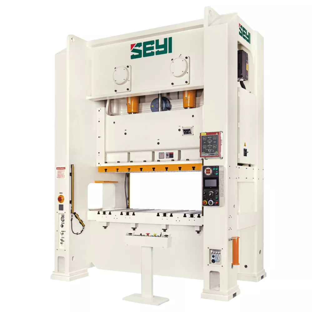
Model | SNS1-88 | SNS1-121 | SNS1-176 | ||||
Type | S | H | S | H | S | H | |
Capacity | U.S. ton | 88 | 121 | 176 | |||
Stroke Length | in | 5.91 | 3.94 | 7.09 | 4.33 | 7.87 | 5.12 |
Strokes per Minute | SPM | 40~75 | 55~125 | 35~65 | 50~110 | 30~55 | 40~95 |
Tonnage Rating Point | in | 0.20 | 0.20 | 0.24 | |||
Die Height | in | 12.99 | 11.81 | 13.78 | 12.60 | 15.75 | 14.17 |
Slide Adjustment | in | 3.15 | 3.54 | 3.94 | |||
Slide Area(LRxFB) | in | 27.56×18.11 | 31.50×20.47 | 35.43×22.83 | |||
Diameter of Shank Hole | in | ø2 | ø2 | ø2.56 | |||
Bolster Area(LRxFB) | in | 35.43×26.77 | 35.43×18.11 | 39.37×26.77 | 39.37×20.47 | 45.28×29.92 | 45.28×33.62 |
Bolster Thickness | in | 5.51 | 6.10 | 6.50 | |||
Bolster Height(w/o Mounts) | in | 35.43 | 35.43 | 37.01 | 35.43 | ||
Main Motor | HP x P | 10×4 | 15×4 | 20×4 | |||
Slide Adjustment Motor | HP x P | 0.5×4 | 0.5×4 | 1×4 | |||
Window Opening(FBxUD) | in | 17.32×11.02 | 14.57×9.84 | 19.69×11.81 | 16.54×10.63 | 22.05×13.78 | 18.50×12.20 |
Foot Print | in | 56.30×57.87 | 56.30×55.91 | 61.42×62.99 | 61.42×61.02 | 67.72×70.08 | 67.72×68.11 |
Floor Space Required | in | 64.17×68.50 | 69.49×73.82 | 75×80.91 | |||
Press Height(w/o Mounts) | in | 108.86 | 118.11 | 130.71 | 129.13 | ||
Max. Upper Die Weight | LBS | 660 | 880 | 880 | |||
Required Air Pressure | PSI | 71 | 71 | 71 | |||
Die Cushion (Option) | |||||||
Capacity | U.S. ton | 6.6 | – | 6.6 | – | 8.8 | – |
Stroke Length | in | 3.74 | – | 3.74 | – | 4.33 | – |
Cushion Pad Area (LR × FB) | in | 18.90×13.39 | – | 18.90×13.39 | – | 22.05×14.57 | – |
Model | SNS1-220 | SNS1-275 | SNS1-330 | ||||
Type | S | H | S | H | S | H | |
Capacity | U.S. ton | 220 | 275 | 330 | |||
Stroke Length | in | 8.66 | 5.91 | 9.84 | 7.09 | 11.02 | 7.09 |
Strokes per Minute | SPM | 25~45 | 35~80 | 22~40 | 30~60 | 20~35 | 25~50 |
Tonnage Rating Point | in | 0.24 | 0.24 | 0.24 | |||
Die Height | in | 17.72 | 15.75 | 17.72 | 15.75 | 19.69 | 15.75 |
Slide Adjustment | in | 4.33 | 4.72 | 4.72 | |||
Slide Area(LRxFB) | in | 39.37×25.59 | 43.31×28.35 | 45.28×31.50 | |||
Diameter of Shank Hole | in | ø2.56 | ø2.56 | ø2.56 | |||
Bolster Area(LRxFB) | in | 49.21×33.07 | 49.21×26.77 | 53.15×35.43 | 53.15×29.53 | 55.12×41.34 | 55.12×33.46 |
Bolster Thickness | in | 7.09 | 7.09 | 7.87 | |||
Bolster Height(w/o Mounts) | in | 40.16 | 39.37 | 40.16 | 39.37 | 40.94 | 40.16 |
Main Motor | HP x P | 25×4 | 30×4 | 40×4 | |||
Slide Adjustment Motor | HP x P | 1×4 | 1×4 | 2×4 | |||
Window Opening(FBxUD) | in | 24.41×15.75 | 20.47×13.78 | 26.77×15.75 | 22.44×13.78 | 29.92×17.72 | 25.59×13.78 |
Foot Print | in | 73.62×77.95 | 73.62×75.98 | 78.35×84.65 | 78.35×82.68 | 81.50×90.43 | 81.50×88.46 |
Floor Space Required | in | 80.91×88.39 | 85.63×98.43 | 88.78×101.57 | |||
Press Height(w/o Mounts) | in | 147.24 | 146.46 | 158.27 | 157.48 | 165.35 | 158.66 |
Max. Upper Die Weight | LBS | 1760 | 2200 | 2700 | |||
Required Air Pressure | PSI | 71 | 71 | 71 | |||
Die Cushion (Option) | |||||||
Capacity | U.S. ton | 11 | – | 11 | – | 15.4 | – |
Stroke Length | in | 5.12 | – | 5.12 | – | 5.51 | – |
Cushion Pad Area (LR × FB) | in | 27.56×17.72 | – | 27.56×17.72 | – | 27.56×17.72 | – |
Model | SNS2-176 | SNS2-220 | SNS2-275 | ||||||
Type | S | H | S | H | S | H | |||
Capacity | U.S. ton | 176 | 220 | 275 | |||||
Stroke Length | in | 7.87 | 5.12 | 9.06 | 5.91 | 9.84 | 7.09 | ||
Strokes per Minute | SPM | 30~60 | 40~90 | 25~50 | 35~70 | 22~40 | 30~60 | ||
Tonnage Rating Point | in | 0.24 | 0.16 | 0.28 | 0.16 | 0.28 | 0.20 | ||
Die Height | in | 17.72 | 15.75 | 19.69 | 17.72 | 21.65 | 17.72 | ||
Slide Adjustment | in | 3.94 | 3.94 | 4.72 | |||||
Slide Area(LRxFB) | in | 61.42×25.59 | 72.83×29.53 | 1 | 86.61×32.28 | ||||
2 | 98.43×32.28 | ||||||||
Diameter of Shank Hole | in | Φ2.01×3 | Φ2.01×3 | Φ2.01×3 | |||||
Bolster Area(LRxFB) | in | 72.83×29.92 | 86.61×33.07 | 1 | 98.43×36.22 | ||||
2 | 110.24×36.22 | ||||||||
Bolster Thickness | in | 6.30 | 6.69 | 7.09 | |||||
Bolster Height | in | 37.10 | 39.37 | 1 | 43.31 | ||||
2 | 45.28 | ||||||||
Main Motor | HP×P | 20×4 | 25×4 | 30×4 | |||||
Slide Adjustment Motor | HP×P | 2×4 | 2×4 | 2×4 | |||||
Window Opening(FB) | in | 25.98 | 29.13 | 32.28 | |||||
Window Opening(UD) | in | 15.75 | 12.60 | 17.72 | 13.78 | 18.11 | 13.78 | ||
Foot Print | in | 102.36×56.30 | 115.35×64.96 | 1 | 129.53×70.47 | ||||
2 | 145.28×70.47 | ||||||||
Floor Space Required | in | 106.50×92.32 | 119.88×98.03 | 1 | 133.46×100.59 | ||||
2 | 149.21×100.59 | ||||||||
Press Height | in | 138.19 | 135.83 | 152.95 | 150.79 | 1 | 164.57 | 3 | 159.45 |
2 | 166.54 | 4 | 161.42 | ||||||
Max. Upper Die Weight | LBS | 3086 | 4409 | 1 | 4850 | ||||
2 | 5510 | ||||||||
Required Air Pressure | PSI | 85 | 85 | 85 | |||||
Die Cushion (Option) | |||||||||
Capacity | U.S. ton | 8.8×2 | – | 11×2 | – | 15.4×2 | – | ||
Stroke Length | in | 4.33 | – | 5.12 | – | 5.51 | – | ||
Cushion Pad Area (LR × FB) | in | 22.05×14.57×2 | 27.56×17.72×2 | 27.56×17.72×2 | |||||
Model | SNS2-330 | SNS2-440 | SNS2-550 | |||||||||||
Type | S | H | S | H | S | H | ||||||||
Capacity | U.S. ton | 330 | 440 | 550 | ||||||||||
Stroke Length | in | 11.02 | 7.09 | 11.81 | 7.87 | 11.81 | 7.87 | |||||||
Strokes per Minute | SPM | 20~40 | 25~50 | 20~40 | 25~50 | 20~40 | 25~50 | |||||||
Tonnage Rating Point | in | 0.28 | 0.20 | 0.28 | 0.24 | 0.28 | 0.24 | |||||||
Die Height | in | 21.65 | 17.72 | 23.62 | 17.72 | 23.62 | 17.72 | |||||||
Slide Adjustment | in | 4.72 | 4.72 | 4.72 | ||||||||||
Slide Area(LRxFB) | in | 1 | 86.61×35.43 | 1 | 86.61×39.37 | 1 | 86.61×43.31 | |||||||
2 | 98.43×35.43 | 2 | 98.43×39.37 | 2 | 98.43×43.31 | |||||||||
3 | 110.24×35.43 | 3 | 110.24×39.37 | 3 | 110.24×43.31 | |||||||||
4 | 122.05×35.43 | 4 | 122.05×39.37 | 4 | 122.05×43.31 | |||||||||
Diameter of Shank Hole | in | Φ2.01×3 | Φ2.01×3 | Φ2.01×3 | ||||||||||
Bolster Area(LRxFB) | in | 1 | 98.43×39.37 | 1 | 98.43×43.31 | 1 | 98.43×47.24 | |||||||
2 | 110.24×39.37 | 2 | 110.24×43.31 | 2 | 110.24×47.24 | |||||||||
3 | 122.05×39.37 | 3 | 122.05×43.31 | 3 | 122.05×47.24 | |||||||||
4 | 133.86×39.37 | 4 | 133.86×43.31 | 4 | 133.86×47.24 | |||||||||
Bolster Thickness | in | 7.87 | 7.87 | 7.87 | ||||||||||
Bolster Height | in | 1、2 | 45.28 | 49.21 | 49.21 | |||||||||
3、4 | 49.21 | |||||||||||||
Main Motor | HP×P | 40×4 | 50×4 | 60×4 | ||||||||||
Slide Adjustment Motor | HP×P | 2×4 | 2×4 | 2×4 | ||||||||||
Window Opening(FB) | in | 35.43 | 39.37 | 43.31 | ||||||||||
Window Opening(UD) | in | 19.69 | 13.78 | 21.65 | 15.75 | 21.65 | 15.75 | |||||||
Foot Print | in | 1 | 133.46×73.62 | 1 | 134.25×81.50 | 1 | 144.49×85.43 | |||||||
2 | 145.28×73.62 | 2 | 146.06×81.50 | 2 | 156.30×85.43 | |||||||||
3 | 157.48×73.62 | 3 | 157.87×81.50 | 3 | 159.45×85.43 | |||||||||
4 | 169.29×73.62 | 4 | 169.69×81.50 | 4 | 171.26×85.43 | |||||||||
Floor Space Required | in | 1 | 137.40×104.92 | 1 | 139.57×116.34 | 1 | 149.61×126.38 | |||||||
2 | 149.21×104.92 | 2 | 151.38×116.34 | 2 | 161.42×126.38 | |||||||||
3 | 161.42×101.38 | 3 | 163.19×116.34 | 3 | 164.57×126.38 | |||||||||
4 | 173.23×101.38 | 4 | 175×116.34 | 4 | 176.38×126.38 | |||||||||
Press Height | in | 1,2 | 177.36 | 1,2 | 171.46 | 1,2 | 189.76 | 1,2 | 179.72 | 1,2 | 197.64 | 1,2 | 187.80 | |
3,4 | 181.89 | 3,4 | 175.98 | 3,4 | 191.54 | 3,4 | 185.63 | 3,4 | 197.64 | 3,4 | 187.80 | |||
Max. Upper Die Weight | LBS | 1,2 | 6172 | 1,2 | 6614 | 1,2 | 7055 | |||||||
3,4 | 6614 | 3,4 | 7055 | 3,4 | 7496 | |||||||||
Required Air Pressure | PSI | 85 | 85 | 85 | ||||||||||
Die Cushion (Option) | ||||||||||||||
Capacity | U.S. ton | 15.4×2 | – | 15.4×2 | – | 15.4×2 | – | |||||||
Stroke Length | in | 5.51 | – | 5.51 | – | 5.51 | – | |||||||
Cushion Pad Area (LR × FB) | in | 27.56×17.72×2 | 27.56×17.72×2 | 27.56×17.72×2 | ||||||||||
※ For special specifications or requirements of 1100T or above, please contact your local supplier.
※ This specification is subject to change without notice.
This is generally applicable for blanking, punching, bending and forming process on small single work of thin steel plate and progressive die parts, which can connect with single press, progressive die, mechanical Robot or added with transfer system.
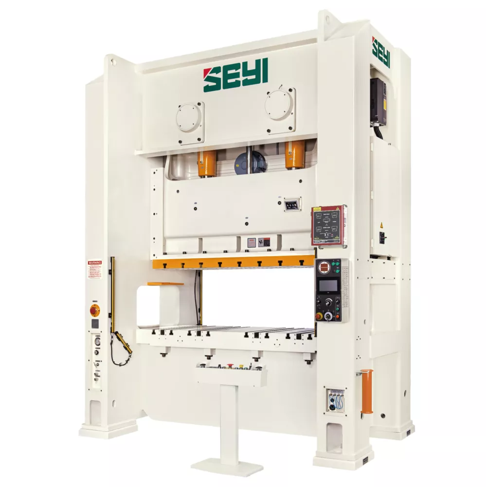
Model | SLS1-88 | SLS1-121 | SLS1-176 | ||||
Type | S | H | S | H | S | H | |
Capacity | U.S. ton | 88 | 121 | 176 | |||
Stroke Length | in | 5.91 | 3.94 | 7.09 | 4.33 | 7.87 | 5.12 |
Strokes per Minute | SPM | 40~80 | 55~110 | 35~65 | 50~110 | 30~55 | 40~85 |
Tonnage Rating Point | in | 0.20 | 0.20 | 0.24 | |||
Die Height | in | 12.99 | 11.81 | 13.78 | 12.60 | 15.75 | 14.17 |
Slide Adjustment | in | 3.15 | 3.54 | 3.94 | |||
Slide Area(LRxFB) | in | 27.56×18.11 | 31.50×20.47 | 35.43×22.83 | |||
Diameter of Shank Hole | in | ø2 | ø2 | ø2.56 | |||
Bolster Area(LRxFB) | in | 35.43×26.77 | 35.43×18.11 | 39.37×26.77 | 39.37×20.47 | 45.28×29.92 | 45.28×33.62 |
Bolster Thickness | in | 5.51 | 6.10 | 6.50 | |||
Bolster Height(w/o Mounts) | in | 35.43 | 35.43 | 37.01 | 35.43 | ||
Main Motor | HP x P | 10×4 | 15×4 | 20×4 | |||
Slide Adjustment Motor | HP x P | 0.5×4 | 0.5×4 | 1×4 | |||
Window Opening(FBxUD) | in | 17.32×11.02 | 14.57×9.84 | 19.69×11.81 | 16.54×10.63 | 22.05×13.78 | 18.50×12.20 |
Foot Print | in | 56.30×57.87 | 56.30×55.91 | 61.42×62.99 | 61.42×61.02 | 67.72×70.08 | 67.72×68.11 |
Floor Space Required | in | 64.17×68.50 | 69.49×73.82 | 75×80.91 | |||
Press Height(w/o Mounts) | in | 108.86 | 118.11 | 130.71 | 129.13 | ||
Max. Upper Die Weight | LBS | 660 | 880 | 880 | |||
Required Air Pressure | PSI | 71 | 71 | 71 | |||
Die Cushion (Option) | |||||||
Capacity | U.S. ton | 6.6 | – | 6.6 | – | 8.8 | – |
Stroke Length | in | 3.74 | – | 3.74 | – | 4.33 | – |
Cushion Pad Area (LR × FB) | in | 18.90×13.39 | – | 18.90×13.39 | – | 22.05×14.57 | – |
Model | SLS1-220 | SLS1-275 | SLS1-330 | ||||
Type | S | H | S | H | S | H | |
Capacity | U.S. ton | 220 | 275 | 330 | |||
Stroke Length | in | 8.66 | 5.91 | 9.84 | 7.09 | 11.02 | 7.09 |
Strokes per Minute | SPM | 25~45 | 35~70 | 22~40 | 30~65 | 20~35 | 25~50 |
Tonnage Rating Point | in | 0.24 | 0.24 | 0.24 | |||
Die Height | in | 17.72 | 15.75 | 17.72 | 15.75 | 19.69 | 15.75 |
Slide Adjustment | in | 4.33 | 4.72 | 4.72 | |||
Slide Area(LRxFB) | in | 39.37×25.59 | 43.31×28.35 | 45.28×31.50 | |||
Diameter of Shank Hole | in | ø2.56 | ø2.56 | ø2.56 | |||
Bolster Area(LRxFB) | in | 49.21×33.07 | 49.21×26.77 | 53.15×35.43 | 53.15×29.53 | 55.12×41.34 | 55.12×33.46 |
Bolster Thickness | in | 7.09 | 7.09 | 7.87 | |||
Bolster Height(w/o Mounts) | in | 40.16 | 39.37 | 40.16 | 39.37 | 40.94 | 40.16 |
Main Motor | HP x P | 25×4 | 30×4 | 40×4 | |||
Slide Adjustment Motor | HP x P | 1×4 | 1×4 | 2×4 | |||
Window Opening(FBxUD) | in | 24.41×15.75 | 20.47×13.78 | 26.77×15.75 | 22.44×13.78 | 29.92×17.72 | 25.59×13.78 |
Foot Print | in | 73.62×77.95 | 73.62×75.98 | 78.35×84.65 | 78.35×82.68 | 81.50×90.43 | 81.50×88.46 |
Floor Space Required | in | 80.91×88.39 | 85.63×98.43 | 88.78×101.57 | |||
Press Height(w/o Mounts) | in | 147.24 | 146.46 | 158.27 | 157.48 | 165.35 | 158.66 |
Max. Upper Die Weight | LBS | 1760 | 2200 | 2700 | |||
Required Air Pressure | PSI | 71 | 71 | 71 | |||
Die Cushion (Option) | |||||||
Capacity | U.S. ton | 11 | – | 11 | – | 15.4 | – |
Stroke Length | in | 5.12 | – | 5.12 | – | 5.51 | – |
Cushion Pad Area (LR × FB) | in | 27.56×17.72 | – | 27.56×17.72 | – | 27.56×17.72 | – |
Model | SLS2-176 | SLS2-220 | SLS2-275 | ||||||
Type | S | H | S | H | S | H | |||
Capacity | U.S. ton | 176 | 220 | 275 | |||||
Stroke Length | in | 7.87 | 5.12 | 9.06 | 5.91 | 9.84 | 5.91 | ||
Strokes per Minute | SPM | 30~55 | 40~90 | 25~50 | 35~70 | 22~40 | 30~60 | ||
Tonnage Rating Point | in | 0.24 | 0.20 | 0.28 | 0.20 | 0.28 | 0.24 | ||
Die Height | in | 17.72 | 15.75 | 19.69 | 17.72 | 21.65 | 17.72 | ||
Slide Adjustment | in | 3.94 | 3.94 | 4.72 | |||||
Slide Area(LRxFB) | in | 61.42×25.59 | 72.83×29.53 | 1 | 86.61×32.28 | ||||
2 | 98.43×32.28 | ||||||||
Diameter of Shank Hole | in | Φ2.01×3 | Φ2.01×3 | Φ2.01×3 | |||||
Bolster Area(LRxFB) | in | 72.83×29.92 | 86.61×33.07 | 1 | 98.43×36.22 | ||||
2 | 110.24×36.22 | ||||||||
Bolster Thickness | in | 6.30 | 6.69 | 7.09 | |||||
Bolster Height | in | 37.40 | 39.37 | 1 | 43.31 | ||||
2 | 45.28 | ||||||||
Main Motor | HP×P | 20×4 | 25×4 | 30×4 | |||||
Slide Adjustment Motor | HP×P | 2×4 | 2×4 | 2×4 | |||||
Window Opening(FB) | in | 25.98 | 29.13 | 32.28 | |||||
Window Opening(UD) | in | 15.75 | 12.60 | 17.72 | 13.78 | 18.11 | 13.78 | ||
Foot Print | in | 102.36×61.42 | 115.35×64.96 | 1 | 129.53×72.83 | ||||
2 | 145.28×72.83 | ||||||||
Floor Space Required | in | 105.32×94.69 | 118.31×98.23 | 1 | 132.48×106.10 | ||||
2 | 148.23×106.10 | ||||||||
Press Height | in | 145.67 | 143.31 | 158.46 | 156.10 | 1 | 168.70 | 3 | 163.39 |
2 | 170.67 | 4 | 172.05 | ||||||
Max. Upper Die Weight | LBS | 3086 | 4409 | 1 | 4850 | ||||
2 | 5511 | ||||||||
Required Air Pressure | PSI | 85 | 85 | 85 | |||||
Die Cushion (Option) | |||||||||
Capacity | U.S. ton | 8.8×2 | – | 11×2 | – | 15.4×2 | – | ||
Stroke Length | in | 4.33 | – | 5.12 | – | 5.51 | – | ||
Cushion Pad Area (LR × FB) | in | 22.05×14.57×2 | 27.56×17.72×2 | 27.56×17.72×2 | |||||
Model | SLS2-330 | SLS2-440 | SLS2-550 | |||||||||||
Type | S | H | S | H | S | H | ||||||||
Capacity | U.S. ton | 330 | 440 | 550 | ||||||||||
Stroke Length | in | 11.02 | 5.91 | 11.81 | 7.87 | 11.81 | 7.87 | |||||||
Strokes per Minute | SPM | 20~35 | 25~50 | 15~35 | 25~45 | 15~30 | 25~40 | |||||||
Tonnage Rating Point | in | 0.28 | 0.28 | 0.28 | 0.28 | 0.28 | 0.28 | |||||||
Die Height | in | 21.65 | 17.72 | 23.62 | 17.72 | 23.62 | 17.72 | |||||||
Slide Adjustment | in | 4.72 | 4.72 | 4.72 | ||||||||||
Slide Area(LRxFB) | in | 1 | 86.61×35.43 | 1 | 86.61×39.37 | 1 | 86.61×43.31 | |||||||
2 | 98.43×35.43 | 2 | 98.43×39.37 | 2 | 98.43×43.31 | |||||||||
3 | 110.24×35.43 | 3 | 110.24×39.37 | 3 | 110.24×43.31 | |||||||||
4 | 122.05×35.43 | 4 | 122.05×39.37 | 4 | 122.05×43.31 | |||||||||
Diameter of Shank Hole | in | Φ2.01×3 | Φ2.01×3 | Φ2.01×3 | ||||||||||
Bolster Area(LRxFB) | in | 1 | 98.43×39.37 | 1 | 98.43×43.31 | 1 | 98.43×47.24 | |||||||
2 | 110.24×39.37 | 2 | 110.24×43.31 | 2 | 110.24×47.24 | |||||||||
3 | 122.05×39.37 | 3 | 122.05×43.31 | 3 | 122.05×47.24 | |||||||||
4 | 133.86×39.37 | 4 | 133.86×43.31 | 4 | 133.86×47.24 | |||||||||
Bolster Thickness | in | 7.87 | 7.87 | 7.87 | ||||||||||
Bolster Height | in | 1、2 | 45.28 | 49.21 | 49.21 | |||||||||
3、4 | 49.21 | |||||||||||||
Main Motor | HP×P | 40×4 | 50×4 | 60×4 | ||||||||||
Slide Adjustment Motor | HP×P | 2×4 | 2×4 | 2×4 | ||||||||||
Window Opening(FB) | in | 35.43 | 39.37 | 43.31 | ||||||||||
Window Opening(UD) | in | 19.69 | 13.78 | 21.65 | 15.75 | 21.65 | 15.75 | |||||||
Foot Print | in | 1 | 133.46×75.98 | 1 | 134.25×81.50 | 1 | 144.49×85.43 | |||||||
2 | 145.28×75.98 | 2 | 146.06×81.50 | 2 | 156.30×85.43 | |||||||||
3 | 157.48×75.98 | 3 | 157.87×81.50 | 3 | 159.45×85.43 | |||||||||
4 | 169.29×75.98 | 4 | 169.69×81.50 | 4 | 171.26×85.43 | |||||||||
Floor Space Required | in | 1 | 137.40×109.45 | 1 | 137.20×124.41 | 1 | 147.44×128.54 | |||||||
2 | 148.23×109.45 | 2 | 149.02×124.41 | 2 | 160.43×128.54 | |||||||||
3 | 160.43×110.43 | 3 | 160.83×124.41 | 3 | 172.24×128.54 | |||||||||
4 | 172.24×110.43 | 4 | 172.64×124.41 | 4 | 184.06×128.54 | |||||||||
Press Height | in | 1,2 | 177.36 | 1,2 | 171.46 | 1,2 | 193.31 | 1,2 | 187.80 | 1,2 | 200.98 | 1,2 | 195.08 | |
3,4 | 187.60 | 3,4 | 183.66 | 3,4 | 196.46 | 3,4 | 190.55 | 3,4 | 203.74 | 3,4 | 197.83 | |||
Max. Upper Die Weight | LBS | 1,2 | 6172 | 1,2 | 6614 | 1,2 | 7055 | |||||||
3,4 | 6614 | 3,4 | 7055 | 3,4 | 7496 | |||||||||
Required Air Pressure | PSI | 85 | 85 | 85 | ||||||||||
Die Cushion (Option) | ||||||||||||||
Capacity | U.S. ton | 15.4×2 | – | 15.4×2 | – | 15.4×2 | – | |||||||
Stroke Length | in | 5.51 | – | 5.51 | – | 5.51 | – | |||||||
Cushion Pad Area (LR × FB) | in | 27.56×17.72×2 | 27.56×17.72×2 | 27.56×17.72×2 | ||||||||||
※ For special specifications or requirements of 1100T or above, please contact your local supplier.
※ This specification is subject to change without notice.
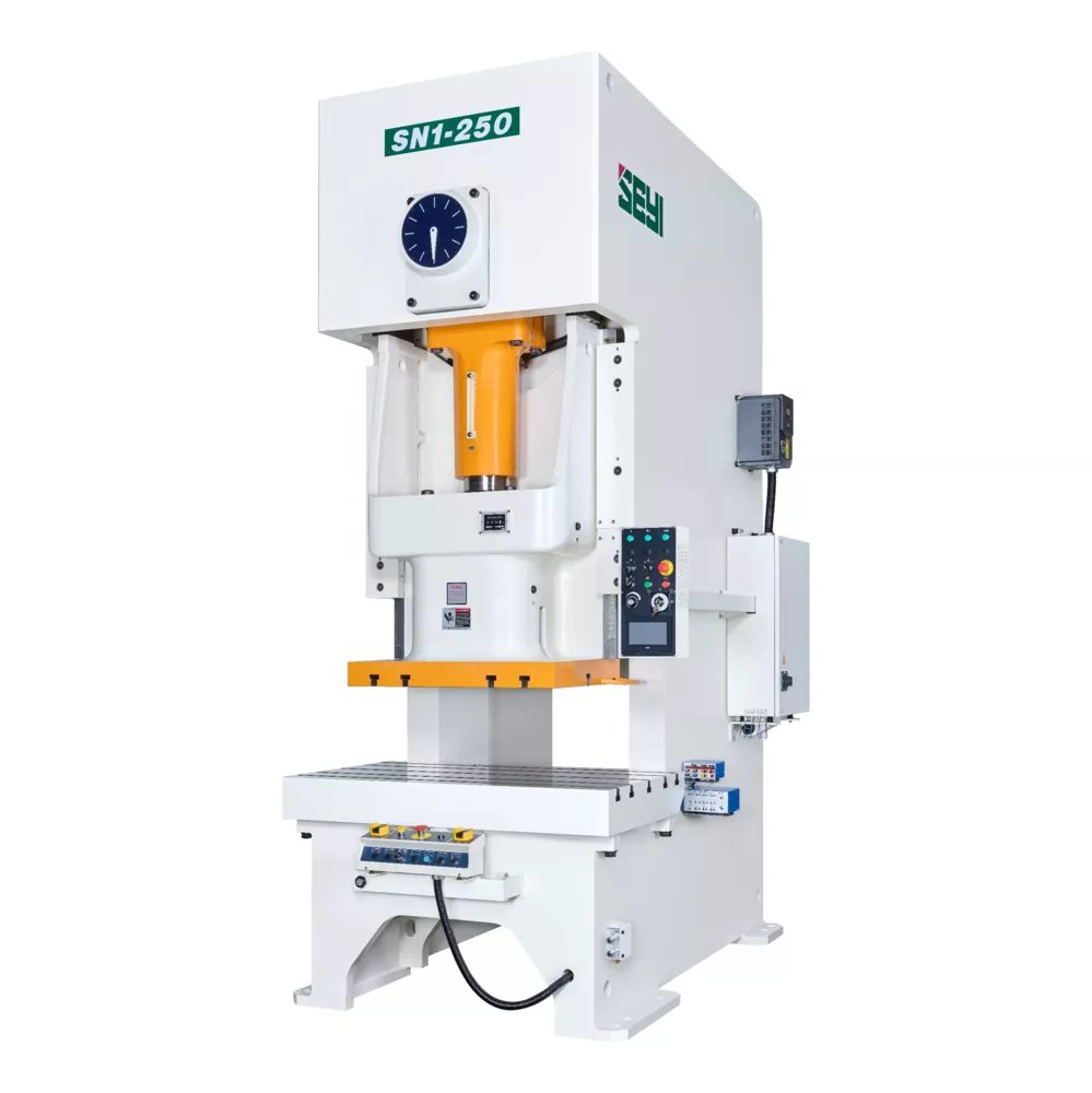
This is generally applicable for blanking, punching, bending and forming process on small single work of thin steel plate and progressive die parts, which can connect with single press, progressive die, mechanical arm or added with transfer system.
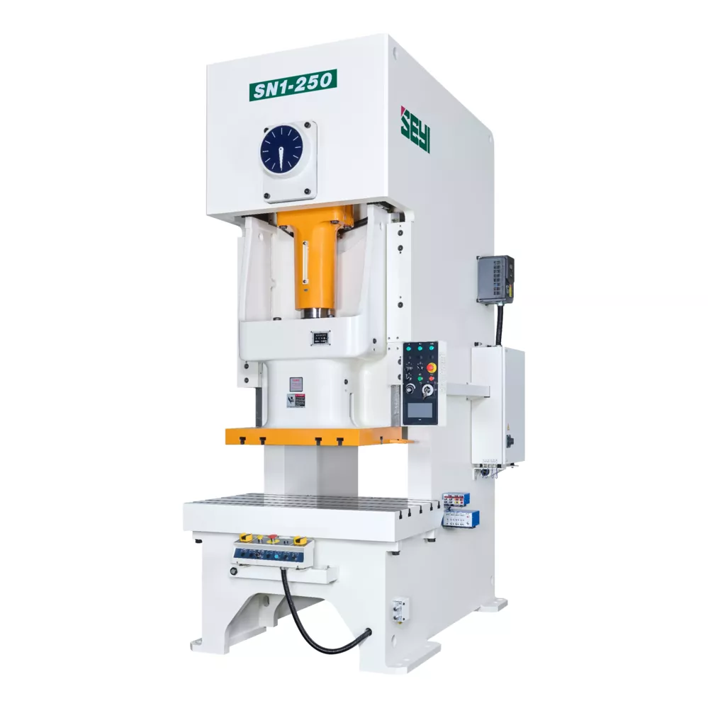
Model | SN1-28 | SN1-39 | ||||||
Type | S | H | P | S | H | P | ||
Capacity | U.S. ton | 28 | 39 | |||||
Stroke Length | in | 3.15 | 1.97 | 1.38 | 3.54 | 2.36 | 1.57 | |
Strokes per Minute | Fixed Speed | SPM | 90 | 110 | 140 | 80 | 100 | 130 |
Variable Speed | 70-110 | 80-140 | 80-180 | 60-105 | 70-140 | 80-180 | ||
Tonnage Rating Point | in | 0.13 | 0.09 | 0.13 | 0.09 | |||
Die Height | in | 9.06 | 7.87 | 9.84 | 8.66 | |||
Slide Adjustment | in | 1.97 | 1.97 | |||||
Slide Area(LRxFB) | in | 12.99×9.84 | 14.96×11.81 | |||||
Diameter of Shank Hole | in | Φ1.50 | Φ2 | |||||
Bolster Area(LRxFB) | in | 27.56×12.60 | 30.71×15.75 | |||||
Bolster Thickness | in | 3.35 | 3.94 | |||||
Bolster Height | in | 31.50 | 31.50 | |||||
Frame-Inside Distance | in | 15.28 | 19.13 | |||||
Frame-Gap Distance | in | 6.69 | 8.27 | |||||
P.T.O. Shaft Position | in | 13.82×38.70×15.08 | 15.87×42.05×15.94 | |||||
Main Motor | Fixed Speed | HPxP | 5×4 | 5×4 | ||||
Variable Speed | 5×4 | 5×4 | ||||||
Slide Adjustment Motor | HPxP | — | — | |||||
Foot Print | in | 28.35×41.65 | 32.68×44.29 | |||||
Position of Anchor Bolts | in | 24.41×34.57 | 28.74×36.42 | |||||
Floor Space Required | in | 34.45×53.54 | 38.78×56.10 | |||||
Press Height | in | 81.10 | 86.02 | |||||
Required Air Pressure | PSI | 71 | 71 | |||||
Die Cushion | Capacity | kN | 2.42 | — | — | 2.42 | — | — |
Stroke Length | mm | 1.97 | — | — | 1.97 | — | — | |
Cushion Pad Area(LRxFB) | mm | 11.61×8.27 | — | — | 11.61×8.27 | — | — | |
Model | SN1-50 | SN1-66 | ||||||
Type | S | H | P | S | H | P | ||
Capacity | U.S. ton | 50 | 66 | |||||
Stroke Length | in | 4.33 | 2.76 | 1.77 | 5.12 | 3.15 | 1.97 | |
Strokes per Minute | Fixed Speed | SPM | 70 | 90 | 120 | 60 | 80 | 100 |
Variable Speed | 50-85 | 60-120 | 80-160 | 40-85 | 55-110 | 70-150 | ||
Tonnage Rating Point | in | 0.13 | 0.09 | 0.16 | 0.09 | |||
Die Height | in | 10.63 | 9.45 | 11.81 | 10.63 | |||
Slide Adjustment | in | 2.36 | 2.76 | |||||
Slide Area(LRxFB) | in | 16.93×13.78 | 18.90×15.75 | |||||
Diameter of Shank Hole | in | Φ2 | Φ2 | |||||
Bolster Area(LRxFB) | in | 33.07×17.32 | 35.43×20.47 | |||||
Bolster Thickness | in | 4.53 | 5.12 | |||||
Bolster Height | in | 31.50 | 35.43 | |||||
Frame-Inside Distance | in | 20.31 | 21.42 | |||||
Frame-Gap Distance | in | 9.06 | 10.63 | |||||
P.T.O. Shaft Position | in | 16.85×45.59×17.20 | 17.72×50.59×18.82 | |||||
Main Motor | Fixed Speed | HPxP | 5×4 | 7.5×4 | ||||
Variable Speed | 5×4 | 7.5×4 | ||||||
Slide Adjustment Motor | HPxP | — | 0.4×4 | |||||
Foot Print | in | 35.04×47.64 | 37.01×51.77 | |||||
Position of Anchor Bolts | in | 31.10×39.76 | 33.07×43.90 | |||||
Floor Space Required | in | 40.75×59.45 | 42.72×63.78 | |||||
Press Height | in | 90.16 | 100.00 | |||||
Required Air Pressure | PSI | 71 | 71 | |||||
Die Cushion | Capacity | kN | 3.85 | — | — | 3.85 | — | — |
Stroke Length | mm | 2.76 | — | — | 2.76 | — | — | |
Cushion Pad Area(LRxFB) | mm | 13.39×9.21 | — | — | 13.39×9.21 | — | — | |
Model | SN1-88 | SN1-121 | ||||||
Type | S | H | P | S | H | P | ||
Capacity | U.S. ton | 88 | 121 | |||||
Stroke Length | in | 5.91 | 3.94 | 2.36 | 7.09 | 4.33 | 2.76 | |
Strokes per Minute | Fixed Speed | SPM | 60 | 80 | 100 | 50 | 70 | 90 |
Variable Speed | 40-85 | 50-100 | 65-150 | 35-75 | 45-100 | 60-135 | ||
Tonnage Rating Point | in | 0.20 | 0.13 | 0.20 | 0.13 | |||
Die Height | in | 12.99 | 11.81 | 13.78 | 12.60 | |||
Slide Adjustment | in | 3.15 | 3.54 | |||||
Slide Area(LRxFB) | in | 22.05×18.11 | 25.59×20.47 | |||||
Diameter of Shank Hole | in | Φ2 | Φ2 | |||||
Bolster Area(LRxFB) | in | 41.34×23.62 | 45.28×26.77 | |||||
Bolster Thickness | in | 5.51 | 6.10 | |||||
Bolster Height | in | 35.43 | 35.43 | |||||
Frame-Inside Distance | in | 24.17 | 26.38 | |||||
Frame-Gap Distance | in | 12.20 | 13.78 | |||||
P.T.O. Shaft Position | in | 19.96×56.89×20.16 | 23.46×64.17×24.17 | |||||
Main Motor | Fixed Speed | HPxP | 7.5×4 | 10×4 | ||||
Variable Speed | 10×4 | 10×4 | 15×4 | |||||
Slide Adjustment Motor | HPxP | 0.4×4 | 0.4×4 | |||||
Foot Print | in | 41.34×58.27 | 45.67×66.14 | |||||
Position of Anchor Bolts | in | 37.40×48.43 | 41.73×54.33 | |||||
Floor Space Required | in | 47.05×70.28 | 51.57×78.15 | |||||
Press Height | in | 108.46 | 117.72 | |||||
Required Air Pressure | PSI | 71 | 71 | |||||
Die Cushion | Capacity | kN | 6.60 | — | — | 8.80 | — | — |
Stroke Length | mm | 3.15 | — | — | 3.54 | — | — | |
Cushion Pad Area(LRxFB) | mm | 16.14×10.24 | — | — | 18.90×11.81 | — | — | |
Model | SN1-176 | SN1-220 | ||||||
Type | S | H | P | S | H | P | ||
Capacity | U.S. ton | 176 | 220 | |||||
Stroke Length | in | 7.87 | 5.12 | 3.15 | 8.66 | 5.91 | 3.54 | |
Strokes per Minute | Fixed Speed | SPM | 40 | 60 | 80 | 35 | 50 | 65 |
Variable Speed | 30-50 | 35-70 | 50-100 | 25-55 | 30-70 | 40-95 | ||
Tonnage Rating Point | in | 0.24 | 0.16 | 0.24 | 0.16 | |||
Die Height | in | 15.75 | 14.17 | 17.72 | 15.75 | |||
Slide Adjustment | in | 3.94 | 4.33 | |||||
Slide Area(LRxFB) | in | 28.35×22.83 | 33.86×25.59 | |||||
Diameter of Shank Hole | in | Φ2.56 | Φ2.56 | |||||
Bolster Area(LRxFB) | in | 49.21×29.92 | 55.12×33.07 | |||||
Bolster Thickness | in | 6.50 | 7.09 | |||||
Bolster Height | in | 35.43 | 39.37 | |||||
Frame-Inside Distance | in | 28.74 | 35.43 | |||||
Frame-Gap Distance | in | 15.35 | 16.93 | |||||
P.T.O. Shaft Position | in | 25.43×71.22×27.01 | 29.76×81.38×28.58 | |||||
Main Motor | Fixed Speed | HPxP | 15×4 | 20×4 | ||||
Variable Speed | 15×4 | 20×4 | 20×4 | |||||
Slide Adjustment Motor | HPxP | 0.7×4 | 0.7×4 | |||||
Foot Print | in | 51.18×78.15 | 58.27×83.19 | |||||
Position of Anchor Bolts | in | 46.46×65.16 | 53.54×69.02 | |||||
Floor Space Required | in | 59.45×90.16 | 66.54×95.08 | |||||
Press Height | in | 128.74 | 146.65 | |||||
Required Air Pressure | PSI | 71 | 71 | |||||
Die Cushion | Capacity | kN | 11.00 | — | — | 15.40 | — | — |
Stroke Length | mm | 3.94 | — | — | 4.33 | — | — | |
Cushion Pad Area(LRxFB) | mm | 21.26×13.39 | — | — | 25.20×17.32 | — | — | |
Model | SN1-275 | SN1-330 | ||||||
Type | S | H | P | S | H | P | ||
Capacity | U.S. ton | 275 | 330 | |||||
Stroke Length | in | 9.84 | 7.09 | 3.94 | 9.84 | 7.09 | ||
Strokes per Minute | Fixed Speed | SPM | 30 | 45 | 55 | 30 | 45 | 55 |
Variable Speed | 22-50 | 30-60 | 30-80 | 20-40 | 25-50 | 30-70 | ||
Tonnage Rating Point | in | 0.24 | 0.16 | 0.24 | 0.16 | |||
Die Height | in | 17.72 | 15.75 | 19.69 | 15.75 | |||
Slide Adjustment | in | 4.72 | 4.72 | |||||
Slide Area(LRxFB) | in | 37.80×28.35 | 39.37×29.53 | |||||
Diameter of Shank Hole | in | Φ2.56 | Φ2.56 | |||||
Bolster Area(LRxFB) | in | 59.06×35.43 | 1600×900 | |||||
Bolster Thickness | in | 7.09 | 7.87 | |||||
Bolster Height | in | 39.37 | 40.94 | |||||
Frame-Inside Distance | in | 38.19 | 39.76 | |||||
Frame-Gap Distance | in | 18.11 | 18.11 | |||||
P.T.O. Shaft Position | in | 31.34×89.06×33.23 | 33.31×97.17×36.22 | |||||
Main Motor | Fixed Speed | HPxP | 25×4 | 22×4 | ||||
Variable Speed | 25×4 | 22×4 | ||||||
Slide Adjustment Motor | HPxP | 0.7×4 | 1.5×4 | |||||
Foot Print | in | 61.42×94.49 | 65.35×94.49 | |||||
Position of Anchor Bolts | in | 56.69×78.74 | 60.63×78.74 | |||||
Floor Space Required | in | 69.69×106.50 | 78.19×107.56 | |||||
Press Height | in | 157.68 | 173.46 | |||||
Required Air Pressure | PSI | 71 | 71 | |||||
Die Cushion | Capacity | kN | 15.40 | — | — | 15.40 | ― | ― |
Stroke Length | mm | 4.72 | — | — | 4.72 | ― | ― | |
Cushion Pad Area(LRxFB) | mm | 29.13×21.26 | — | — | 29.13×21.26 | ― | ― | |
Model | SN2-121 | SN2-176 | SN2-220 | ||||||
Type | S | H | S | H | S | H | |||
Capacity | U.S. ton | 121 | 176 | 220 | |||||
Stroke Length | in | 7.09 | 4.33 | 7.87 | 5.12 | 9.06 | 5.91 | ||
Strokes per Minute | Fixed Speed | SPM | 50 | 70 | 40 | 60 | 35 | 50 | |
Variable Speed | 35~65 | 45~90 | 30~60 | 35~75 | 25~50 | 30~60 | |||
Tonnage Rating Point | in | 0.20 | 0.24 | 0.28 | |||||
Die Height | in | 15.75 | 13.78 | 17.72 | 15.75 | 19.69 | 17.72 | ||
Slide Adjustment | in | 3.54 | 3.94 | 4.33 | |||||
Slide Area(LRxFB) | in | 56.30×20.47 | 61.42×22.83 | 72.83×25.59 | |||||
Diameter of Shank Hole | in | Φ2.01×3 | Φ2.01×3 | Φ2.01×3 | |||||
Bolster Area(LRxFB) | in | 74.02×26.77 | 80.31×29.92 | 95.28×33.07 | |||||
Bolster Thickness | in | 5.91 | 6.30 | 6.69 | |||||
Bolster Height | in | 35.43 | 37.40 | 39.37 | |||||
Frame-Inside Distance | in | 57.87 | 62.60 | 75.98 | |||||
Frame-Gap Distance | in | 13.78 | 15.35 | 16.93 | |||||
P.T.O. Shaft Position | in | 39.57×66.34×24.21 | 39.57×62.99×24.21 | 42.72×73.03×25.98 | 42.72×69.69×25.98 | 49.61×82.95×27.95 | 49.61×79.41×27.95 | ||
Main Motor | HPxP | 10×4 | 15×4 | 15×4 | 20×4 | 20×4 | |||
Slide Adjustment Motor | HPxP | 1×4 | 1×4 | 2×4 | |||||
Foot Print | in | 77.17×69.29 | 77.17×67.13 | 85.43×79.92 | 85.43×77.56 | 99.21×85.24 | 99.21×83.27 | ||
Position of Anchor Bolts | in | 73.23×55.51 | 73.23×53.35 | 80.71×62.60 | 80.71×60.24 | 94.49×67.91 | 94.49×65.94 | ||
Floor Space Required | in | 86.22×71.26 | 86.22×71.26 | 93.50×82.09 | 93.50×82.09 | 107.28×87.80 | 107.28×87.80 | ||
Press Height | in | 122.44 | 119.09 | 133.07 | 129.72 | 148.03 | 144.49 | ||
Required Air Pressure | PSI | 71 | 71 | 71 | |||||
Die Cushion | Capacity | 6.6×2 | — | 8.8×2 | — | 11×2 | — | ||
Stroke Length | 3.74 | — | 4.83 | — | 5.12 | — | |||
Cushion Pad Area(LRxFB) | 18.90×13.39×2 | — | 22.05×14.57×2 | — | 27.56×17.72×2 | — | |||
Model | SN2-275 | SN2-330 | |||||
Type | S | H | S | H | |||
Capacity | U.S. ton | 275 | 330 | ||||
Stroke Length | in | 9.84 | 7.09 | 11.02 | 7.09 | ||
Strokes per Minute | Fixed Speed | SPM | 30 | 45 | 30 | 45 | |
Variable Speed | 22~45 | 30~50 | 20~35 | 30~50 | |||
Tonnage Rating Point | in | 0.28 | 0.28 | ||||
Die Height | in | 21.65 | 17.72 | 21.65 | 17.72 | ||
Slide Adjustment | in | 4.72 | 4.72 | ||||
Slide Area(LRxFB) | in | 82.68×27.56 | 82.68×31.50 | ||||
Diameter of Shank Hole | in | Φ2.01×3 | Φ2.01×3 | ||||
Bolster Area(LRxFB) | in | 106.30×36.22 | 106.30×37.01 | ||||
Bolster Thickness | in | 7.09 | 7.87 | ||||
Bolster Height | in | 43.31 | 43.31 | ||||
Frame-Inside Distance | in | 86.22 | 85.83 | ||||
Frame-Gap Distance | in | 18.50 | 18.90 | ||||
P.T.O. Shaft Position | in | 55.31×90.75×30.31 | 55.31×85.43×30.31 | 55.91×95.87×31.50 | 55.91×89.96×31.50 | ||
Main Motor | HPxP | 30×4 | 30×4 | ||||
Slide Adjustment Motor | HPxP | 2×4 | 2×4 | ||||
Foot Print | in | 110.63×97.24 | 110.63×94.29 | 111.81×101.18 | 111.81×97.24 | ||
Position of Anchor Bolts | in | 105.91×77.56 | 105.91×74.61 | 107.09×80.12 | 107.09×76.18 | ||
Floor Space Required | in | 118.70×99.61 | 118.70×99.61 | 119.88×102.36 | 119.88×102.36 | ||
Press Height | in | 163.39 | 158.07 | 172.44 | 166.54 | ||
Required Air Pressure | PSI | 71 | 71 | ||||
Die Cushion | Capacity | 15.4×2 | — | 15.4×2 | — | ||
Stroke Length | 5.51 | — | 5.51 | — | |||
Cushion Pad Area(LRxFB) | 27.56×17.72×2 | — | 27.56×17.72×2 | — | |||
※ This specification is subject to change without notice.
This is generally applicable for blanking, punching, bending and forming process on small size parts produced from progressive die pressing, or single work steel plates of more than 6mm in thickness for heavy duty, which can connect with progressive die and also single punch.
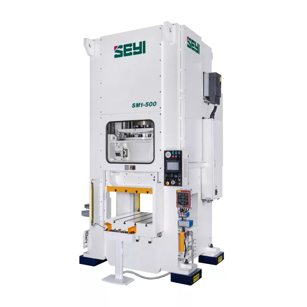
Model | SM1-330 | SM1-550 | SM1-715 | SM1-880 | |||
Type | S | H | S | H | S | S | |
Capacity | U.S.Ton | 330 | 550 | 715 | 880 | ||
Stroke Length | in | 9.84 | 4.72 | 11.81 | 5.91 | 11.81 | 300 |
Stroke per Minute | SPM | 20~50 | 40~70 | 20~40 | 30~55 | 20~35 | 15~30 |
Tonnage Rating Point | in | 0.51 | 0.26 | 0.51 | 0.26 | 0.51 | 0.51 |
Die Height | in | 23.62 | 15.75 | 25.59 | 15.75 | 27.56 | 29.53 |
Slide Adjustment | in | 5.91 | 5.91 | 5.91 | 5.91 | ||
Slide Area(LRxFB) | in x in | 39.37 x 35.43 | 47.24 x 43.3 | 51.18 x 47.24 | 59.05 x 51.18 | ||
Bolster Area(LRxFB) | in x in | 39.37 x 39.37 | 47.24 x 47.24 | 51.18 x 51.18 | 59.05 x 59.05 | ||
Bolster Thickness | mm | 7.09 | 9.84 | 9.84 | 9.84 | ||
Bolster Height(w/ Mounts) | in | 41.73 | 41.73 | 43.31 | 47.24 | ||
Max. Upper Die Weight | LBS | 1100 | 2200 | 3300 | 4400 | ||
Main Motor | HP×P | 50 x 4 | 60 x 4 | 75 x 4 | 100 x 4 | ||
Slide Adjustment Motor | HP×P | 2 x 4 | 2 x 4 | 3 x 6 | 3 x 6 | ||
Window Opening(FBxUD) | in x in | 23.62 x 17.17 | 23.62 x 11.81 | 27.56 x 21.65 | 27.56 x 15.74 | 31.50 x 23.62 | 117.32 x 75.20 |
Press Height | in | 181.10 | 169.29 | 188.98 | 173.23 | 200.79 | 236.22 |
Fundation Bolts Postion | in x in | 78.81 x 49.21 | 86.61 x 52.95 | 98.42 x 64.96 | 117.32 x 75.20 | ||
Required Floor Space | in x in | 93.30 x 104.33 | 101.18 x 15.16 | 112.99 x 133.07 | 131.89 x 145.28 | ||
Required Air Pressure | PSI | 71 | |||||
※ This specification is subject to change without notice.
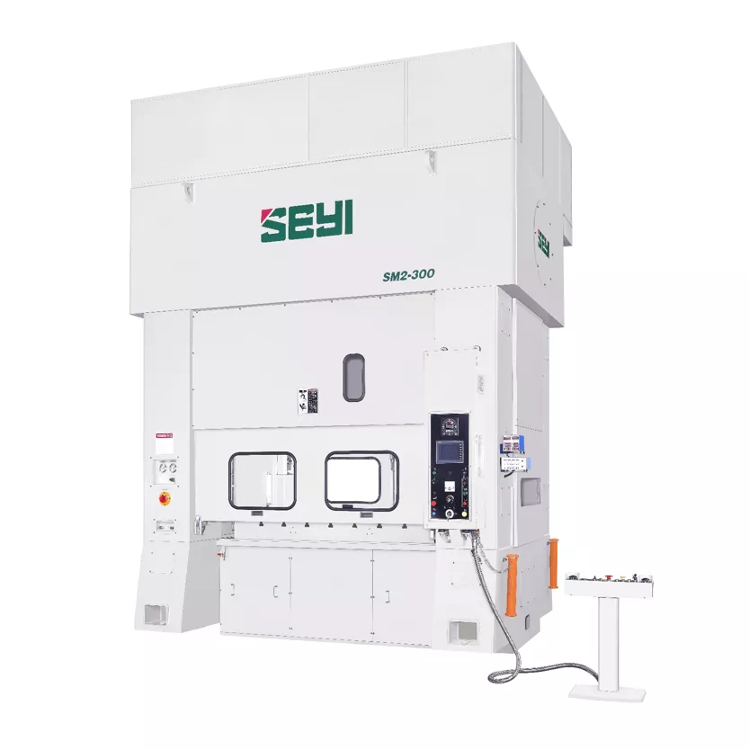
This is generally applicable for blanking, punching, bending and forming process on small size but large quantity of parts produced from progressive die pressing, which can connect with progressive die or added with transfer system.
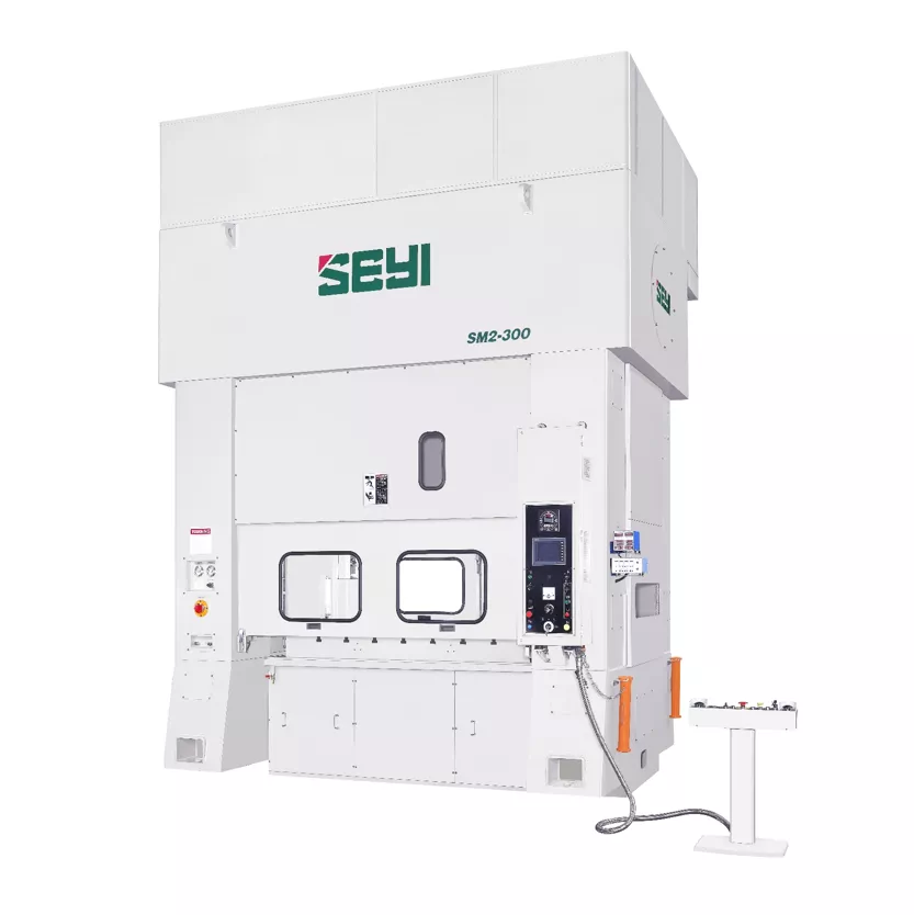
Model | SM2-220 | SM2-330 | SM2-440 | SM2-660 | ||
Tonnage Capacity | U.S.Ton | 220 | 330 | 440 | 660 | |
Stroke Length | in | 7.87 | 7.87 | 7.87 | 9.84 | |
Stroke per Minute | SPM | 50~120 | 40~100 | 30~80 | 30~70 | |
Tonnage Rating Point | in | 0.26 | 0.26 | 0.26 | 0.39 | |
Die Height | in | 17.72 | 21.65 | 25.59 | 29.53 | |
Slide Adjustment | in | 3.94 | 3.94 | 3.94 | 5.91 | |
Slide Area(LRxFB) | 1 | in | 59.05 x 35.43 | 70.87 x 39.37 | 82.68 x 43.31 | 94.49 x 49.21 |
2 | 70.86 x 35.43 | 82.68 x 39.37 | 94.49 x 43.31 | 106.3 x 49.21 | ||
3 | 82.67 x 35.43 | 94.49 x 39.37 | 106.3 x 43.31 | 118.11 x 49.21 | ||
Bolster Area(LRxFB) | 1 | in | 59.05 x 39.37 | 70.87 x 43.31 | 70.87 x 47.24 | 94.49 x 55.12 |
2 | 70.86 x 39.37 | 82.68 x 43.31 | 82.68 x 47.24 | 106.3x 55.12 | ||
3 | 82.67 x 39.37 | 94.49 x 43.31 | 106.3 x 47.24 | 118.11 x 55.12 | ||
Bolster Thickness | in | 7.09 | 7.09 | 9.84 | 9.84 | |
Bolster Height(w/ Mounts) | in | 39.37 | 45.28 | 49.27 | 33.46 (w/ Foundation) | |
Max. Upper Die Weight | LBS | 2200 | 3300 | 6600 | 6600 | |
Main Motor | HP×P | 40×4 | 50×4 | 60×4 | 100×4 | |
Window Opening (FBxUD) | in | 27.55 x 9.84 | 31.5 x 9.84 | 35.43 x 9.84 | 41.34 x 9.84 | |
Press Height | in | 173.62 | 196.85 | 216.54 | 251.97 (from FL) | |
Required Air Pressure | PSI | 71.11 | ||||
※ This specification is subject to change without notice.